Ice energy device

A conversion device and pole technology, which is applied in the direction of display devices, instruments, machines/engines, etc., can solve the problems of passersby turning a blind eye, complex structure, inaccuracy, etc., and achieve the effect of low operating cost, accurate display location, and accurate display content

Pending Publication Date: 2017-06-20
谢宇翔
View PDF11 Cites 1 Cited by
  • Summary
  • Abstract
  • Description
  • Claims
  • Application Information

AI Technical Summary

Problems solved by technology

All of the above methods have their disadvantages: the long-term display of the first sign can only serve as a reminder, telling drivers that they should have this concept and awareness, and long-term display may cause passers-by to turn a blind eye; the second method is accurate, but not In time, it is often a late-morning display. Basically, it is placed by the traffic police after a car accident. The third type is basically accurate but not accurate. It can only be displayed in places with display screens according to the weather forecast. The point is not necessarily at the freezing point, the structure is complicated and the cost is high

Method used


Image

  • Ice energy device
  • Ice energy device
  • Ice energy device

Examples


Embodiment 1

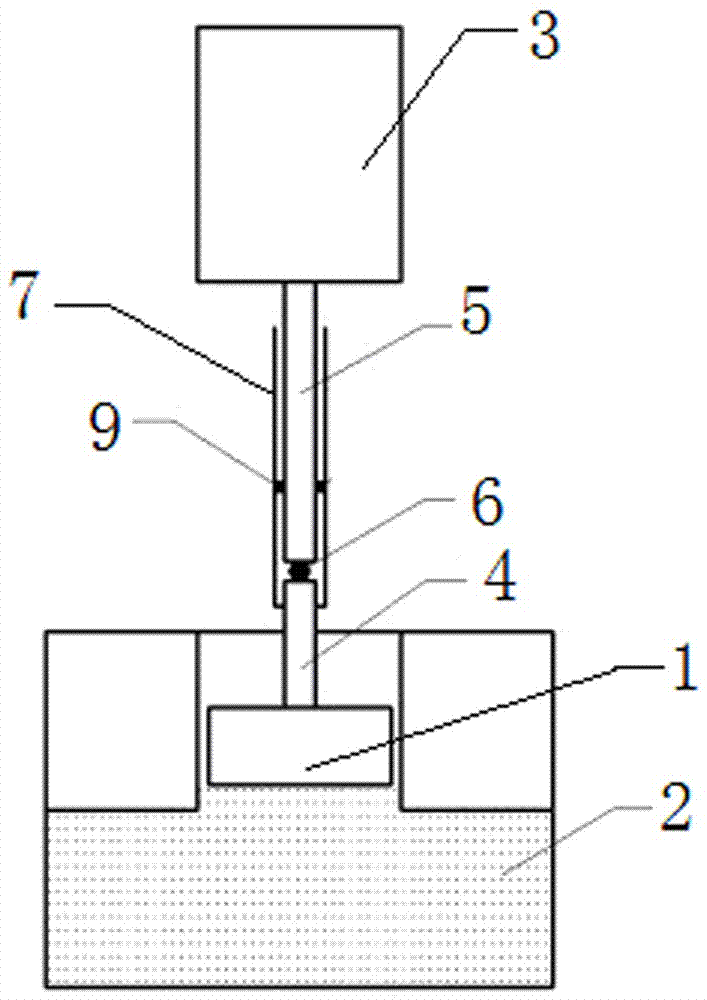
[0031] refer to figure 1 , figure 2 and image 3 , an ice energy device, comprising a closed rigid water tank 2 with a piston 1, the piston 1 being a part of the closed rigid water tank 2, a power conversion device is arranged above the closed rigid water tank 2, and the bottom end of the power conversion device is connected to the piston of the closed rigid water tank 2 1 connected, a warning sign 3 is arranged above the power conversion device, and the top of the power conversion device is connected with the warning sign 3. The piston 1 is driven by the increase in volume of the water in the water-filled rigid water tank 2 with the piston 1 after freezing and the volume decrease when the ice melts as a power source to perform actions.

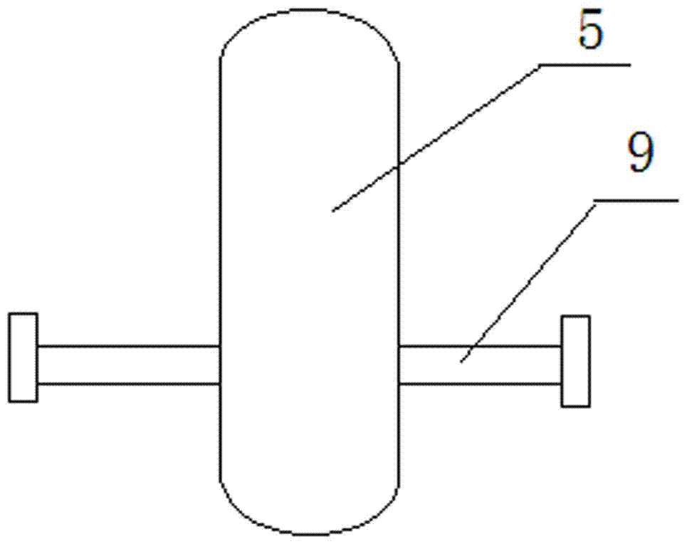
[0032] The power conversion device includes a transmission rod 4, a vertical rod 5, a screw guide, a linear guide mechanism and a coupling device, the top of the vertical rod 5 of the power conversion device is connected with the warning s...

Embodiment 2

[0043] The difference between this embodiment and embodiment 1 is:

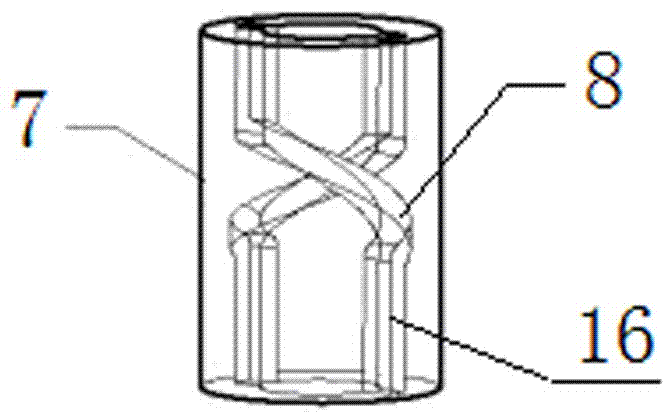
[0044] The spiral through hole 8 is replaced by a spiral groove (not shown in the figure). refer to Figure 4 , the first coupling rod 9 is replaced by a second coupling rod 10 whose length is shorter than that of the first coupling rod 9 . The coupling device is a second coupling rod 10 fixed on the vertical rod 5 , and the end of the second coupling rod 10 extends into the helical groove of the vertical rod outer cover 7 . The two ends of the helical grooves of the pole jacket 7 are provided with first linear grooves (not shown in the figure), and the two first linear grooves communicate with the top of the helical through hole and the bottom end of the helical through hole respectively. A linear groove constitutes a linear guide mechanism.

[0045] All the other are with embodiment 1.

Embodiment 3

[0047] The difference between this embodiment and embodiment 1 is:

[0048] In this embodiment, there is no need to provide a screw hole 8 on the outer cover 7 of the vertical rod, and there is no need to add a first coupling rod 9 to the vertical rod 5 .

[0049] refer to Figure 5 and Figure 6 , the spiral guide device includes a spiral steel belt 11, the spiral steel belt 11 is arranged between the vertical rod 5 and the friction reducing device 6, the top of the spiral steel belt 11 is fixedly connected with the bottom end of the vertical rod 5, and the spiral steel belt The bottom end of 11 is in contact with the friction reducing device 6, the outer periphery of the vertical rod 5 is provided with a vertical rod cover 7, the vertical rod 5 is arranged in the vertical rod cover 7, and the vertical rod cover 7 is horizontally provided with an inner plate used as a coupling device 12. The inner plate 12 is fixedly connected with the outer cover 7 of the pole. The center ...


PUM


Abstract

The invention provides an ice energy device. The principle that the volume of water changes in the solid-liquid phase change process and the characteristic that molecules slide relative to one another when water freezes are used, a closed rigid water tank with a piston is filled with water, and the piston is driven by volume change in a container to move and release energy capable of working. The device comprises the closed rigid water tank which is filled with water and provided with the piston, the piston is one part of the closed rigid water tank, a power conversion device is arranged on the upper portion of the closed rigid water tank, the bottom of the power conversion device is connected with the piston of the closed rigid water tank, a warning board is disposed on the upper side of the power conversion device, and the top of the power conversion device is connected with the warning board. The ice energy device is simple in structure and low in manufacturing cost, once the ice energy device is installed, preset work can be automatically completed when conditions are formed, the ice energy device is not provided with precise parts or electronic parts, the operation cost is low, time display is timely, displayed contents are accurate, a display place is precise, and relevant personnel can be reminded in time to reduce traffic accidents.

Description

technical field [0001] The invention relates to an ice energy device. Background technique [0002] 1: So far, the use of natural energy by humans mainly refers to energy resources that exist in natural forms in nature and have not been processed or converted, such as coal, oil, natural gas, nuclear fuel, wind energy, water energy, solar energy, geothermal energy, ocean energy, tidal energy, etc. The energy generated by water in the solid-liquid phase transition, that is, the ice energy mentioned in this case, has not been utilized, especially the energy generated when water freezes often has a negative impact on production and life. This case tries to use this energy in order to Serving socialist construction. [0003] 2: The content display of the existing icy road traffic indication device is mainly divided into the following types: 1: Fixed road sign reminder, such as: rain, fog, ice and snow weather, when the vehicle passes the bridge, please drive carefully; 2: Tempo...

Claims


Application Information

Patent Timeline
Patent Type & Authority Applications(China)
IPC IPC(8): G09F7/22F03G7/06
CPCG09F7/22F03G7/06
Inventor 谢宇翔
Owner 谢宇翔
Why Eureka
Try Eureka