
Air well technological testing system during full life cycle

A technology of full life cycle and process test, applied in the field of process test system of gas well life cycle, which can solve the problems of verification, low flowback rate, and inability to realize parameters, etc.

Pending Publication Date: 2017-06-20
BC P INC CHINA NAT PETROLEUM CORP +1
View PDF7 Cites 4 Cited by
  • Summary
  • Abstract
  • Description
  • Claims
  • Application Information

AI Technical Summary

Problems solved by technology

[0002] At present, the flowback rate of gas wells is low after production stimulation and reconstruction. During the production process, fluid accumulation at the bottom of the well, serious failure of restrictors and gas lift valves have become the main factors that plague the production of gas fields. Downhole throttling, gas well workover and other operating technologies have been unable to achieve parameter optimization and effect verification due to the lack of necessary test platforms. The technology has been hesitant for many years, and new technologies such as gas well snubbing operations and coiled tubing operations have been tested directly in wells. greater risk

Method used


Image

  • Air well technological testing system during full life cycle
  • Air well technological testing system during full life cycle

Examples


Embodiment 1

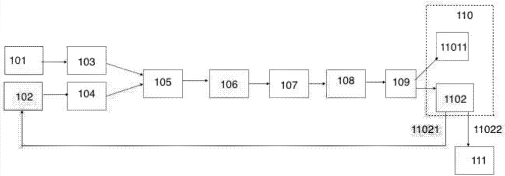
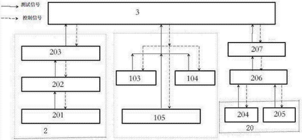
[0018] Such as figure 1 and figure 2 As shown, a gas well life cycle process test system includes an air compressor 101, a water tank 102, a gas storage well 103, a plunger pump 104, a gas-liquid mixing precise control injection system 105, an input manifold 106, and a process test well 107 , throttling manifold 108, automatic separation and metering system 109, noise reduction and filtration recycling system 110, sewage collection 111, downhole multi-point parameter direct reading test interpretation system 2 and visual monitoring operation integration system 3, the air compressor 101 is connected to The gas storage well 103 and the water tank 102 are connected to the plunger pump 104, the gas storage well 103 and the plunger pump 104 are connected to the gas-liquid mixing precise control injection system 105, the gas-liquid mixing precise control injection system 105, the input manifold 106, the process test well 107, Throttle manifold 108, automatic separation and meterin...

Embodiment 2

[0021] Such as figure 1 As shown, on the basis of Example 1, the gas-liquid mixing accurately controls the working pressure of the injection system 105 to 70MPa, the injection flow rate is 0-720m3 / d, the gas volume is 1000-100000N m3 / d, and the mixing ratio is the liquid volume 0-100%, air volume 0-100%, measurement accuracy is 0.5% liquid volume, 1% air volume. It is conducive to carrying out theoretical research, tool performance evaluation and process simulation experiments under close working conditions, and can shorten the development process of processes, tools and equipment. When the gas-liquid mixing precise control injection system 105 is used in test well tests, the two phases of gas and liquid are precisely prepared and mixed according to different proportions, and injected into the process test well; the gas-liquid mixing precise control injection system 105 is controlled by the gas pipeline , infusion manifold, gas-liquid mixing device, control valves and sensors...

Embodiment 3

[0023] Such as figure 1 As shown, on the basis of Example 1-2, the process test well 107 is a double-casing high-inclination process test well, the working pressure is 70Mpa, the wellbore is a high-inclination well, the well depth is 1700m, and the vertical well section is 1200m The inclined well section is 500m long, the vertical well depth is 1500m, and the inclination is 80°. Casing cementing, after passing the pressure test, the 51 / 2" construction casing and 27 / 8" operation tubing are run in. The wellhead adopts KQ78 / 65-7011 valve wellhead, and the input manifold controls from 73 / 4 "Large annulus gas injection, choke manifold controls 51 / 2" casing small annulus and the return gas-liquid mixture in the working tubing; Gas, the throttling manifold controls the return of the gas-liquid mixture from the 73 / 4" large annulus; or others.

[0024] The working pressure of the gas storage well 103 and the plunger pump 104 is 70Mpa. The working pressure of the gas storage well 103...


PUM


Abstract

The invention belongs to the technical field of air well technological testing and particularly provides an air well technological testing system during a full life cycle. The air well technological testing system during the full life cycle comprises an air compressor, a water tank, an air storage well, a plunger pump, an air-liquid mixed accurately-control injecting system, an input manifold, a technological testing well, a throttling manifold, an automatic separating and metering system, a sound eliminating and filtering recycling system, a waste water collector, a down hole multipoint parameter direct reading test and interpreting system and a visualization monitoring and operating integrated system. According to the air well technological testing system during the full life cycle, the problem that parameter optimization and effect verification cannot be achieved due to the fact that the operation technologies such as spray induction and liquor drainage, drainage air recovery, down hole throttle and air well repair lack necessary testing platforms all the time in the down hole operation process is solved, air well technological simulating and testing during the full life cycle can be conducted, wherein the air well technological simulating and testing during the full life cycle comprises construction technological verification tests and operation parameter optimization such as air well liquor drainage after pressing, low-pressure air well spray induction and liquor drainage, drainage air recovery, down hole throttle and the well repair technology and operation parameter optimization as well as technological simulating and testing of operation under the pressure and coiled-tubing operation.

Description

technical field [0001] The invention belongs to the technical field of gas well process test, and in particular relates to a process test system for the whole life cycle of a gas well. Background technique [0002] At present, the flowback rate of gas wells is low after production stimulation and reconstruction. During the production process, fluid accumulation at the bottom of the well, serious failure of restrictors and gas lift valves have become the main factors that plague the production of gas fields. Downhole throttling, gas well workover and other operating technologies have been unable to achieve parameter optimization and effect verification due to the lack of necessary test platforms. The technology has been hesitant for many years, and new technologies such as gas well snubbing operations and coiled tubing operations have been tested directly in wells. greater risk. Contents of the invention [0003] The purpose of the present invention is to provide a process...

Claims


Application Information

Patent Timeline
IPC IPC(8): E21B43/00E21B47/002
CPCE21B43/00E21B47/002
Inventor 孙虎韩静静徐迎新王祖文吴简马小龙张冕陈文博席仲琛谢涛尤文浩严勋
Owner BC P INC CHINA NAT PETROLEUM CORP
Learn More