Anti-shear self restoring pier joint

A technology for self-resetting bridge piers and joints, applied in bridges, bridge parts, bridge construction, etc., can solve the problems of unfavorable horizontal impact force, insufficient safety redundancy, unfavorable anti-collision piers, etc., to achieve simple structure and improve safety redundancy. degree, the effect of improving the seismic performance

Inactive Publication Date: 2017-06-20
CHANGAN UNIV
View PDF4 Cites 8 Cited by
  • Summary
  • Abstract
  • Description
  • Claims
  • Application Information

AI Technical Summary

Problems solved by technology

[0002] Self-resetting bridge piers can improve the seismic performance of bridges as a bridge anti-seismic structure. However, there are some problems in the joints of self-resetting bridge piers at present: 1. The joints of existing self-resetting bridge piers are unfavorable to the shear resistance of bridge piers. The joints of existing self-resetting bridge piers The anti-shearing methods include using the friction force between the pier and the joint to resist shearing, and using the elastic force between the column-type, ball-type, cone-type and other chimeric joints and the pier to resist shearing, but the bottom of the self-resetting pier under the action of the earthquake It will be partially separated from the joint, which is unfavorable to the shear resistance of the pier; 2. The joint of the existing self-resetting pier is unfavorable to the anti-collision of the pier, because the self-resetting pier is disconnected from the joint at the bottom of the pier and is made of unbonded prestressed steel bars It is connected with ductile steel bars, so when a vehicle hits, the existing self-resetting bridge pier joints are unfavorable for the bridge pier to withstand the horizontal impact force; 3. The joints of the existing self-resetting bridge piers are made of unbonded prestressed steel bars and ductile steel bars to resist the bending moment at the bottom of the pier, There is a certain lack of security redundancy

Method used


Image

  • Anti-shear self restoring pier joint
  • Anti-shear self restoring pier joint
  • Anti-shear self restoring pier joint

Examples


Embodiment Construction

[0020] The present invention is described in further detail below in conjunction with accompanying drawing:

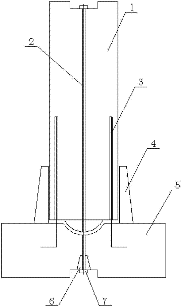
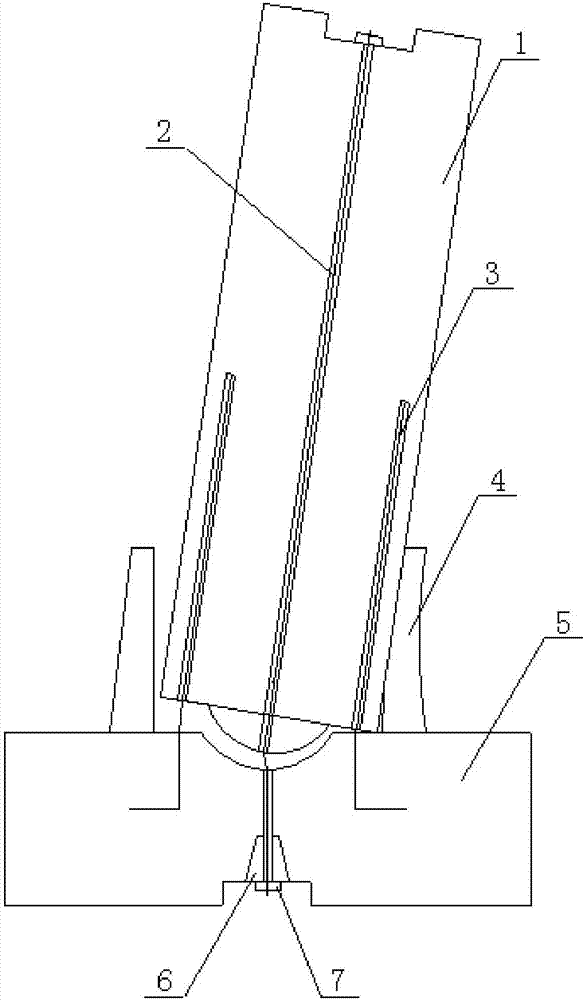
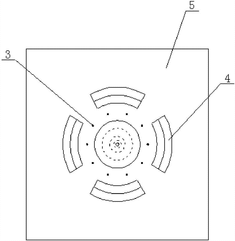
[0021] refer to figure 1 The shear-resistant self-resetting bridge pier joint described in the present invention includes a bridge pier 1, a base 5, an unbonded prestressed steel bar 2, a number of shear components 4 and a number of reserved ductile steel bars 3, the bridge pier 1 and each shear component 4 are all located on the base 5, each shear component 4 is located around the pier 1, the upper end of the unbonded prestressed steel bar 2 is connected with the pier 1, and the lower end of the unbonded prestressed steel bar 2 is connected with the base 5, each The upper ends of the reserved ductile steel bars 3 are connected to the pier 1 , and the lower ends of each reserved ductile steel bars 3 are connected to the base 5 .

[0022] The upper end of the unbonded prestressed steel bar 2 passes through the middle of the bridge pier 1 from bottom to top and is fixed...


PUM


Abstract

The invention discloses an anti-shear self restoring pier joint comprising a pier, a base, an unbonded prestressed steel bar, a plurality of anti-shear components and a plurality of reserved ductile steel bars, wherein the pier and the anti-shear components are positioned on the base; the anti-shear components are positioned around the pier; the upper end of the unbonded prestressed steel bar is connected with the pier and the lower end of the unbonded prestressed steel bar is connected with the base; and the upper end of each reserved ductile steel bar is connected with the pier and the lower end of each reserved ductile steel bar is connected with the base. The anti-shear self restoring pier joint facilitates the anti-shearing and anti-collision of the pier and can effectively improve the safety redundancy of the pier.

Description

technical field [0001] The invention belongs to the technical field of bridges, and relates to a shear-resistant self-resetting bridge pier joint. Background technique [0002] Self-resetting bridge piers can improve the seismic performance of bridges as a bridge anti-seismic structure. However, there are some problems in the joints of self-resetting bridge piers at present: 1. The joints of existing self-resetting bridge piers are unfavorable to the shear resistance of bridge piers. The joints of existing self-resetting bridge piers The anti-shearing methods include using the friction force between the pier and the joint to resist shearing, and using the elastic force between the column-type, ball-type, cone-type and other chimeric joints and the pier to resist shearing, but the bottom of the self-resetting pier under the action of the earthquake It will be partially separated from the joint, which is unfavorable to the shear resistance of the pier; 2. The joint of the exis...

Claims


Application Information

Patent Timeline
IPC IPC(8): E01D19/00E01D19/02
CPCE01D19/00E01D19/02
Inventor 李宇李琛马磊吴桂楠付曜
Owner CHANGAN UNIV
Why Eureka
Try Eureka