
Gate removing structure of injection mold and injection mold

A technology of injection mold and dehydration port, applied in the field of dehydration port structure and injection mold, can solve the problems of unstable structure, easy deformation or burning, increase mold cost, etc., achieve simple and stable structure, improve appearance quality, and save mold cost Effect

Active Publication Date: 2017-06-20
SHENZHEN SKYWORTH PRECISION TECH
View PDF5 Cites 1 Cited by
  • Summary
  • Abstract
  • Description
  • Claims
  • Application Information

AI Technical Summary

Problems solved by technology

However, for large nozzles, both the product and the cold material (parts formed after the plastic in the runner is cooled and formed) are demoulded on the parting line. Therefore, the cold material is still integrated with the product after demoulding, and the nozzle needs to be trimmed. A large rubber mouth print seriously affects the appearance of the product; while using a hot runner increases the cost of the mold; using a three-plate mold with a fine nozzle, the mold will be thicker and the front mold needs a dehydration port, and for deep cavity products, the A plate is thicker , the load bearing of the guide column is too large, it is easy to deform or burn to death, and the structure is not stable enough. If the A plate is too thick, the tonnage of the injection molding machine needs to be increased, causing a lot of inconvenience

Method used


Image

  • Gate removing structure of injection mold and injection mold
  • Gate removing structure of injection mold and injection mold
  • Gate removing structure of injection mold and injection mold

Examples


Embodiment 1

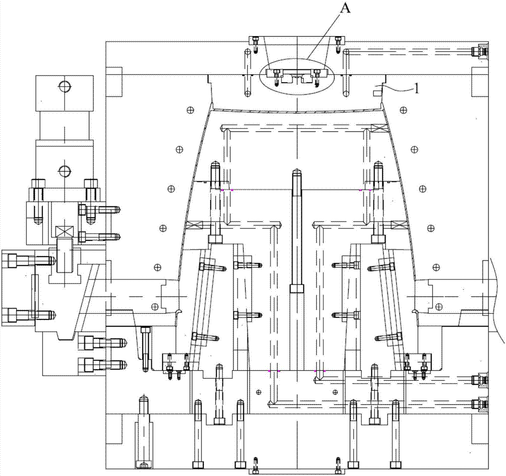
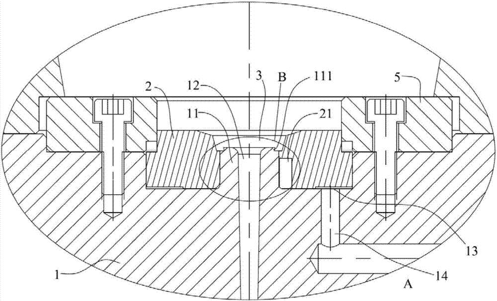
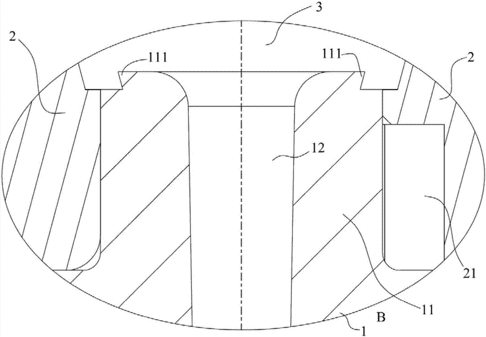
[0025] This embodiment provides a dewatering port structure of an injection mold, such as Figure 1-Figure 4 As shown, it includes a front mold insert 1, a floating insert 2 and a driving structure. The end of the front mold insert 1 near the nozzle is protruded with a boss 11, and the floating insert 2 is sleeved outside the boss 11 and can move along the boss. 11 slides, the boss 11 is provided with an undercut portion 111 whose width becomes larger along the convex direction of the boss 11, and the boss 11 is provided with a flow channel 12 downward from the top surface, and the inner cavity of the floating insert 2 and the boss 11 The top end of the nozzle forms a nozzle area 3 communicating with the flow channel 12, the undercut portion 111 is located in the nozzle area 3, and the driving structure drives the floating insert 2 to slide along the boss 11. This embodiment also provides a kind of injection mold with this dewatering port structure, and its working process is ...

Embodiment 2

[0037] Different from Embodiment 1, in this embodiment, the drive structure includes an ejector that can move along the direction of the boss 11 and a drive that drives the ejector to move. The ejector is located at the bottom of the floating insert 2, and the floating insert There is a through hole in the middle part of the piece 2, and the through hole is sleeved on the boss 11. The through hole is sealed with the side of the boss 11, and the bottom of the through hole is provided with a gap 21 upward. When the floating insert 2 moves upward to the gap 21 When exposed, the gas enters the nozzle area 3 from the gap 21 . In this embodiment, the driving structure of the floating insert 2 is replaced by the ejector and the driving piece, and the floating insert 2 can be directly driven by the mechanical structure to separate the cold material 4. However, in order to better remove the cold material 4 , it is still necessary to eject the cold material 4 with the help of gas, and t...


PUM

PropertyMeasurementUnit
Angleaaaaaaaaaa
Heightaaaaaaaaaa

Abstract

The invention discloses a gate removing structure of an injection mold and the injection mold. The gate removing structure comprises a front mold insert, a floating insert and a driving structure; a boss is arranged at the top end of the front mold insert in a protruding mode; the floating insert is arranged outside the boss in a sleeving mode and can slide along the boss; the boss is provided with an inverted part of which the width is increased in the protruding direction of the boss and further provided with a runner extending downwards from the top surface of the boss; an inner cavity of the floating insert and the top end of the boss form a gate zone communicating with the runner; the inverted part is located in the gate zone; and the driving structure drives the floating insert to slide along the boss. Large molding entrances like a large gate structure do not need to be arranged, a large-area trace at the joint of a product and the runner is avoided, the appearance quality of the product is improved, a three-plate mold does not need to be arranged, only the inverted part and the floating insert are needed, thus, the structure is simple and stable, and the mold cost is reduced.

Description

technical field [0001] The invention relates to the technical field of molds, in particular to a dewatering port structure of an injection mold and the injection mold. Background technique [0002] For injection molding products, especially plastic parts such as drums, basins, boxes, and shaped deep cavities, to avoid surface clamping and meet injection molding requirements, the common practice is to use large spouts or hot runner dispensing ports. And sealing pin, or three-plate mold fine nozzle design, fast filling speed, good pressure holding effect, no or minimal weld lines on the product surface. However, for large nozzles, both the product and the cold material (parts formed after the plastic in the runner is cooled and formed) are demoulded on the parting line. Therefore, the cold material is still integrated with the product after demoulding, and the nozzle needs to be trimmed. A large rubber mouth print seriously affects the appearance of the product; while using a...

Claims


Application Information

Patent Timeline
IPC IPC(8): B29C45/38B29C45/26
CPCB29C45/26B29C45/382
Inventor 袁建忠张松平邓剑锋王国强肖新莉
Owner SHENZHEN SKYWORTH PRECISION TECH
Learn More