Wire cutting mechanism

A wire cutting machine tool and transmission mechanism technology, applied in metal processing equipment, manufacturing tools, electric processing equipment, etc., can solve the problems of increasing maintenance costs, accelerating wear, and reducing motor life, so as to reduce maintenance costs and prolong service life. , the effect of long service life

Inactive Publication Date: 2018-11-02
LUSHAN COLLEGE OF GUANGXI UNIV OF SCI & TECH +1
View PDF7 Cites 0 Cited by
  • Summary
  • Abstract
  • Description
  • Claims
  • Application Information

AI Technical Summary

Problems solved by technology

When starting a motor with a large capacity, it will cause an impact on the power grid and destroy the normal operation of other equipment on the same power grid
In addition, it will have a great impact on the stator coil and rotor squirrel cage of the motor itself, reducing the life of the motor
[0004] 2. The starting torque of the motor is about 2 times of the rated torque when the motor is directly started with full pressure. It has a large impact on the transmission components such as guide rails, gears, and lead screws, which will accelerate wear and tear. Moreover, the motor speed rises rapidly when starting, and the lubricating oil is often not enough. In place in time, affecting the service life of transmission components
[0005] 3. Control the continuous power-on and power-off of the forward and reverse circuits of the motor, which controls the uninterrupted cycle action of electrical components such as contactors, travel switches, and protective appliances. The contacts of the relay are prone to arcing, and even fuse together to produce Misoperation increases maintenance costs
[0006] 4. Since the motor and the wire storage drum are connected by a coupling, the coupling is subject to a large shear force at the moment of frequent forward and reverse rotation of the motor, which affects its transmission accuracy and greatly shortens the coupling. service life

Method used


Image

  • Wire cutting mechanism
  • Wire cutting mechanism

Examples


Embodiment 1

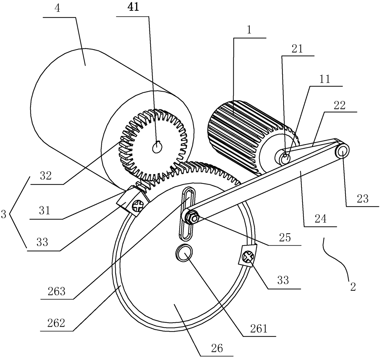
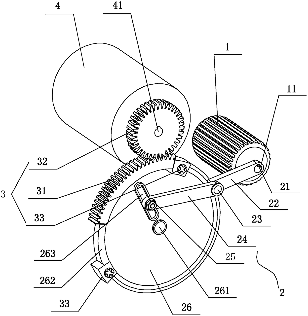
[0037] A wire-feeding mechanism for a wire-cut machine tool, comprising a motor 1, a wire storage tube 4, a crank-rocker mechanism 2, and a rack-and-pinion transmission mechanism 3, the output shaft 11 of the motor is connected to the crank end of the crank-rocker mechanism 2, The rocker end of the crank rocker mechanism 2 is connected with the transmission shaft 41 of the wire storage drum through the rack and pinion transmission mechanism 3 .

[0038] Described crank rocker mechanism 2 comprises crank 22, connecting rod 24, balance wheel 26, and one end of crank 22 is fixed on the output shaft 11 of electric motor by crank fixed key 21, to realize the function of crank; The hinge 23 is connected with one end of the connecting rod 24 to realize the function of the revolving pair; the other end of the connecting rod 24 is connected with the balance wheel 26 through a fastener 25—a fastening nut, and the balance wheel 26 is installed on the balance wheel shaft 261 to realize Th...


PUM


Abstract

A wire-feeding mechanism for a wire-cutting machine tool, relating to an auxiliary device for a wire-cutting machine tool, including a motor, a wire storage barrel, a crank-rocker mechanism, and a rack-and-pinion transmission mechanism. The output shaft of the motor is connected to the crank end of the crank-rocker mechanism , the rocker end of the crank rocker mechanism is connected with the transmission shaft of the wire storage drum through the rack and pinion transmission mechanism. The crank-rocker mechanism includes a crank, a connecting rod, and a balance wheel. One end of the crank is fixed on the output shaft of the motor through a crank fixing key, the other end of the crank is connected to one end of the connecting rod through a hinge, and the other end of the connecting rod is connected by a fastener. It is connected with the balance wheel, and the balance wheel is installed on the balance wheel shaft; the balance wheel is also connected with the transmission shaft of the silk storage drum through a rack and pinion transmission mechanism. The present invention realizes the forward and reverse rotation of the wire storage drum by controlling the crank rocker mechanism by the motor, avoids the frequent forward and reverse rotation of the motor in the prior art, has the advantages of low energy consumption, long service life, low maintenance cost, simple structure and convenient manufacture. Easy to promote and use.

Description

technical field [0001] The invention relates to an auxiliary device of a wire-cutting machine tool, in particular to a wire-feeding mechanism of the wire-cutting machine tool. Background technique [0002] At present, the electrode wire of the wire cutting mechanism on the market is molybdenum wire, and the slender molybdenum wire is wound on the wire storage drum. The wire storage drum is connected with the drive motor through an elastic coupling. On the same horizontal line, the drive motor performs positive and negative rotation, and the positive and negative rotation of the motor is mainly controlled by the left and right stroke bumpers on the wire feeder. The motor drives the wire storage drum between the left and right stroke bumps. Circular reciprocating movement between, this structure has the following problems: [0003] 1. Since the forward and reverse wire walking is realized by the forward rotation-stop-reverse rotation of the motor, and the full-voltage startin...

Claims


Application Information

Patent Timeline
Patent Type & Authority Patents(China)
IPC IPC(8): B23H7/10B23H7/26B23H7/02
CPCB23H7/02B23H7/10B23H7/26
Inventor 农胜隆高尚晗潘宇倩张莹
Owner LUSHAN COLLEGE OF GUANGXI UNIV OF SCI & TECH
Why Eureka
Try Eureka