
A positioner for peritoneal dialysis in nephrology department

The technology of peritoneal dialysis and locator is applied in the field of peritoneal dialysis locator in nephrology department, which can solve the problems of lack of sealing device, pain of secondary intubation of patients, damage of outer tube, etc., and achieves ease of work difficulty, remarkable fixing effect and simple structure. Effect

Inactive Publication Date: 2019-07-05
刘希会
View PDF7 Cites 0 Cited by
  • Summary
  • Abstract
  • Description
  • Claims
  • Application Information

AI Technical Summary

Problems solved by technology

At present, many patients adopt peritoneal dialysis, that is, enter the peritoneal dialysis solution from the outside of the human body through an external tube for peritoneal dialysis to maintain electrolyte balance. The process of peritoneal dialysis is to perfuse the dialysate in series and parallel. The pipeline is evenly perfused into the peritoneal cavity for 2-4 hours, and the dialysate of these metabolic wastes and excess water is released from the peritoneal cavity through the outer tube, and then filled with new peritoneal dialysate, so that the continuous circulation operation can continuously discharge toxins and If there is excess water, the patient needs to permanently install an outer tube on the abdomen. Therefore, the fixation of the outer tube for dialysis is very important. If it cannot be fixed, peritonitis will easily occur. Moreover, if the fixation is not good, the outer tube will be damaged, causing the patient to lose weight. secondary intubation pain
At present, the traditional peritoneal dialysis positioner used in the department of nephrology lacks a sealing device, the process of installing the positioning equipment is troublesome, and the fixation is poor. We propose a peritoneal dialysis positioner used in the department of nephrology.

Method used


Image

  • A positioner for peritoneal dialysis in nephrology department
  • A positioner for peritoneal dialysis in nephrology department
  • A positioner for peritoneal dialysis in nephrology department

Examples


Embodiment Construction

[0016] The following will clearly and completely describe the technical solutions in the embodiments of the present invention with reference to the accompanying drawings in the embodiments of the present invention. Obviously, the described embodiments are only some, not all, embodiments of the present invention. Based on the embodiments of the present invention, all other embodiments obtained by persons of ordinary skill in the art without making creative efforts belong to the protection scope of the present invention.

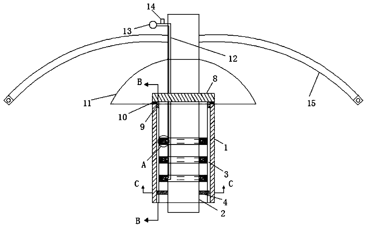
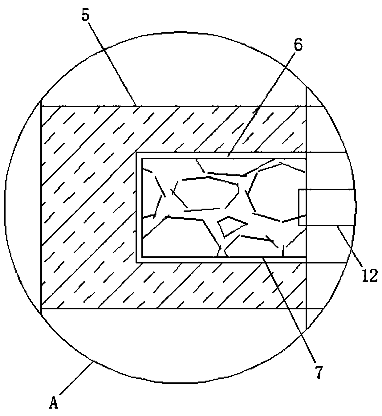
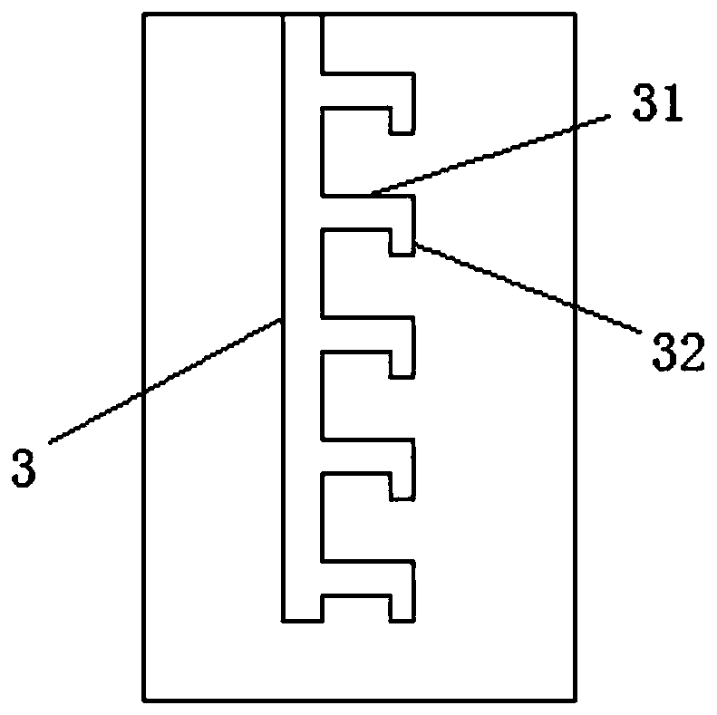
[0017] see Figure 1-4 , the present invention provides a technical solution: a peritoneal dialysis positioner for nephrology, including a fixed pipeline 1 and a dialysis catheter 2, the inner wall of the fixed pipeline 1 is provided with two vertically to fix the centerline of the pipeline 1 It is the first chute 3 of the symmetrical axis, and the inner wall of the fixed pipeline 1 is provided with two rows of second chute 31 with the centerline of the fixed ...


PUM


Abstract

The invention relates to the technical field of peritoneal dialysis locators, in particular to a peritoneal dialysis locator for a nephrology department. The inner wall of a fixed pipe is provided with two rows of second sliding grooves which take the center line of the fixed pipe as a symmetry axis in the vertical direction, locating slots formed in the fixed pipe are connected to the ends, away from first sliding grooves, of the second sliding grooves, multiple elastic rubber sleeves located above sliding rods are connected to the side wall of a dialysis catheter in a sleeving mode, the middles of the ends, connected with the dialysis catheter, of the elastic rubber sleeves are provided with annular grooves, a locating ring is connected to the middle of the dialysis catheter in a sliding and sleeving mode, clamping blocks clamped with the first sliding grooves are connected to the lower end of the locating ring, a sealing washer is connected to the lower end of the locating ring, and waist belts are connected to the two sides, located above a locating sucker, of the dialysis catheter. The peritoneal dialysis locator has the advantages that the dialysis catheter position is adjustable, the fixing effect is significant, and the working difficulty of medical staff is reduced.

Description

technical field [0001] The invention relates to the technical field of a peritoneal dialysis positioner, in particular to a peritoneal dialysis positioner used in nephrology. Background technique [0002] Uremic patients require regular dialysis. At present, many patients adopt peritoneal dialysis, that is, enter the peritoneal dialysis solution from the outside of the human body through an external tube for peritoneal dialysis to maintain electrolyte balance. The process of peritoneal dialysis is to perfuse the dialysate in series and parallel. The pipeline is evenly perfused into the peritoneal cavity for 2-4 hours, and the dialysate of these metabolic wastes and excess water is released from the peritoneal cavity through the outer tube, and then filled with new peritoneal dialysate, so that the continuous circulation operation can continuously discharge toxins and If there is excess water, the patient needs to permanently install an outer tube on the abdomen. Therefore, ...

Claims


Application Information

Patent Timeline
Patent Type & Authority Patents(China)
IPC IPC(8): A61M1/28A61M25/02
CPCA61M1/28A61M25/02A61M2025/0293
Inventor 刘希会左效艳
Owner 刘希会
Learn More