Broach assembly for lathe

A technology of knife components and lathes, which is applied in the direction of broaching machines, broaching machine devices, metal processing machinery parts, etc., can solve the problems of no machine tools, equipment investment and site investment waste, high-priced subcontracting processing, etc., to ensure stability and guarantee The effect of concentricity

Inactive Publication Date: 2015-04-15
宫卫东 +1
View PDF6 Cites 0 Cited by
  • Summary
  • Abstract
  • Description
  • Claims
  • Application Information

AI Technical Summary

Problems solved by technology

[0003] Due to the low proportion of the broaching process in the product processing process, the broaching machine is idle most of the time, resulting in a huge waste of equipment investment and site investment, and because the broaching process has high efficiency and high precision, there is no possibility Alternative machine tools make the use of broaching machines in an embarrassing situation for some small machining companies. Most of them choose high-priced subcontracting processing when encountering broaching processes

Method used


Image

  • Broach assembly for lathe
  • Broach assembly for lathe
  • Broach assembly for lathe

Examples


Embodiment Construction

[0043] In order to make the purpose, technical solution and advantages of the present invention clearer, the technical solution of the present invention will be clearly and completely described below. All other implementations obtained below fall within the protection scope of the present invention.

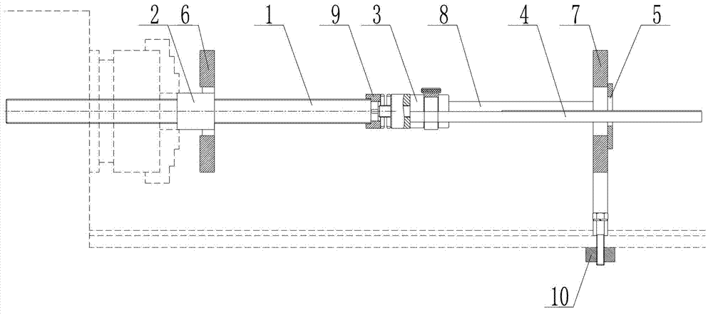
[0044] One embodiment of the present invention provides a broach assembly for a lathe, such as figure 1 As shown, it includes a screw rod 1, a screw nut 2, a guide device, a connecting member 3, a broach 4 and a workpiece fixing device 5;

[0045]The screw 1 and the screw nut 2 are socketed and matched; one end of the screw 1 is connected to the broach 4 through the connecting member 3; the length direction of the broach 4 is the same as the axial direction of the screw 1;

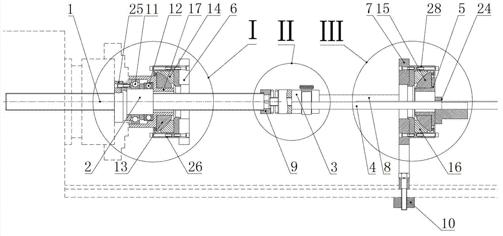
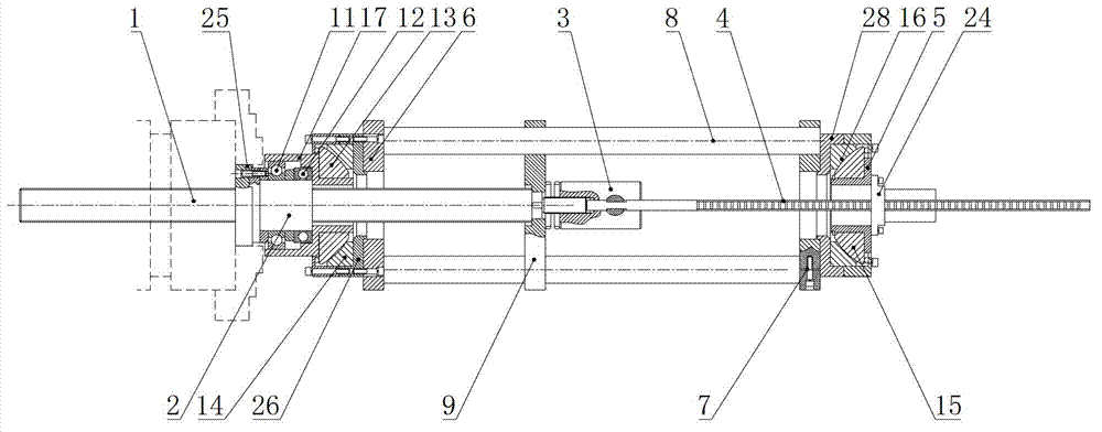
[0046] The guide device includes a front base 6, a rear base 7, a track 8, a guide arm 9 and a fixed member 10 for fixed connection with the lathe;

[0047] The front base 6 is rotatably connected to the ou...


PUM


Abstract

The invention relates to the machining field, particularly to a broach assembly for a lathe. The broach assembly comprises a screw rod, a nut, a guide device, a connecting element, a broach and a workpiece fixing device, wherein the screw rod is in sleeved fit with the nut; one end of the screw rod is connected with the broach through the connecting element; the guide device comprises a front base, a back base, a track, a guide arm and a fixing element which is used for being fixedly connected with the lathe; the front base is rotatably connected with the outer surface of the nut; the back base and the workpiece fixing device are sleeved on the outer side of the broach and far away from the front base sequentially; the back base is connected with the fixing element; the track extends along the axial direction of the screw rod, and two ends of the track are connected with the front base and the back base respectively; the guide arm is slidably connected with the track and capable of sliding along the extending direction of the track; and the end of the screw rod, which is connected with the connecting element is connected with the guide arm. Compared with the prior art, ordinary lathes can achieve functions of broaching machines through the broach assembly.

Description

technical field [0001] The invention relates to the field of machining, in particular to a broach assembly for a lathe. Background technique [0002] The broaching machine is a machine tool used in the machining industry to process round holes, keyways, involutes, square holes, hexagonal holes, spline holes, semicircular holes, and other geometric shapes of special-shaped holes. The operation is simple and labor-saving, the efficiency is high and irreplaceable, and it is generally valued by people. The pulling force ranges from tens of KN to hundreds of KN, the self-weight ranges from several tons to dozens of tons, and the floor area varies from a few square meters to dozens of square meters. [0003] Due to the low proportion of the broaching process in the product processing process, the broaching machine is idle most of the time, resulting in a huge waste of equipment investment and site investment, and because the broaching process has high efficiency and high precisio...

Claims


Application Information

Patent Timeline
Patent Type & Authority Patents(China)
IPC IPC(8): B23D41/08B23Q5/22B23D41/00
Inventor 宫卫东叶文胜
Owner 宫卫东
Why Eureka
Try Eureka