
Low-cost wireless charging passive repeater

A passive repeater and wireless charging technology, applied in the direction of electrical components, circuit devices, etc., can solve the problems of bulkiness and high cost, and achieve the effect of low cost

Inactive Publication Date: 2017-06-13
苏州横空电子科技有限公司
View PDF2 Cites 0 Cited by
  • Summary
  • Abstract
  • Description
  • Claims
  • Application Information

AI Technical Summary

Problems solved by technology

[0003] To sum up, the problem existing in the prior art is: to design a full-featured power transmission unit (PTU) for charging wearable devices, the cost will be relatively high and it will appear cumbersome

Method used


Image

  • Low-cost wireless charging passive repeater
  • Low-cost wireless charging passive repeater
  • Low-cost wireless charging passive repeater

Examples


Embodiment Construction

[0019] In order to make the object, technical solution and advantages of the present invention more clear, the present invention will be further described in detail below in conjunction with the examples. It should be understood that the specific embodiments described here are only used to explain the present invention, not to limit the present invention.

[0020] The application principle of the present invention will be described in detail below in conjunction with the accompanying drawings.

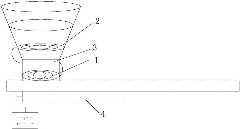
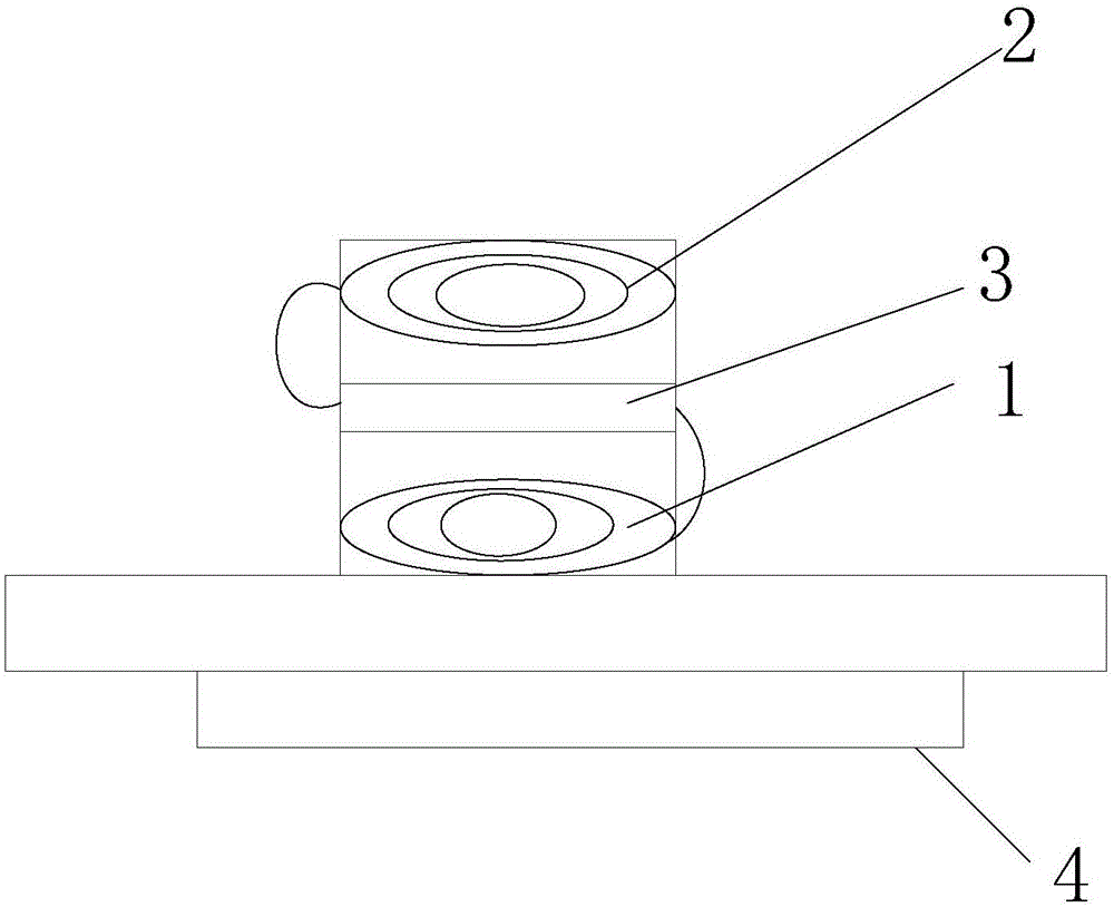
[0021] Such as figure 1 As shown, the low-cost wireless charging passive repeater provided by the embodiment of the present invention includes:

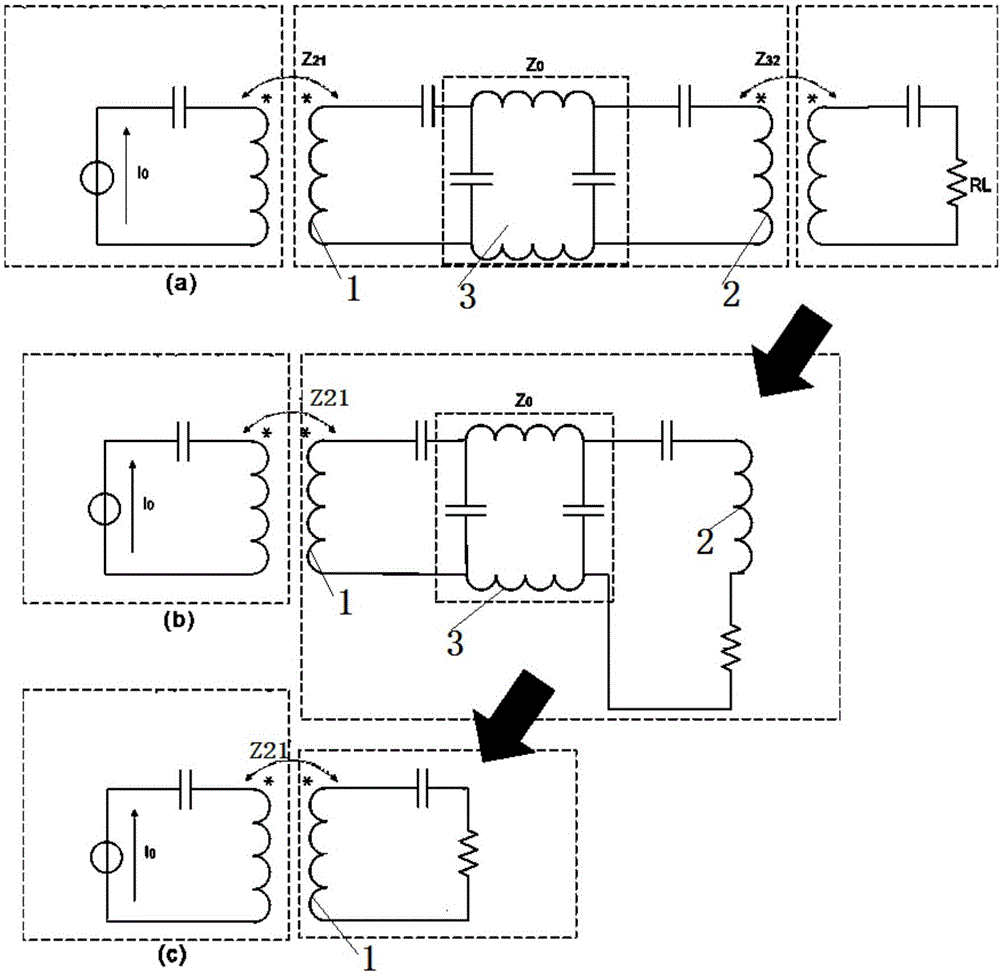
[0022] a primary coil 1, a secondary coil 2 and a quarter-wavelength impedance converter circuit 3;

[0023] The primary and secondary coils are connected by a quarter wave impedance converter circuit.

[0024] The phase difference between the primary coil and the secondary coil is 90 degrees.

[0025] The main coil obtains the magnetic f...


PUM


Abstract

The invention relates to the technical field of wireless charging and discloses a low-cost wireless charging passive repeater comprising a master coil, a secondary coil and a quarter-wavelength impedance converter circuit. The master and secondary coils are connected through the quarter-wavelength impedance converter circuit. The low-cost wireless charging passive repeater combines a charging coil and a passive circuit, realizes a scheme of charging a wearable device by using a conventional wireless charging transmitter (PTU). Compared with a conventional scheme, the passive repeater does not need a circuit or a power supply line.

Description

technical field [0001] The invention belongs to the technical field of wireless charging, in particular to a low-cost wireless charging passive repeater. Background technique [0002] A few days ago, as magnetic resonance wireless charging technology began to be applied to wireless charging of high-power (such as ultrabooks) and low-power (such as wearable) devices, the industry began to realize that using the same power transfer unit (PTU) requires Simultaneously supporting charging of PCs, tablets, mobile phones and wearable devices and providing the same charging distance is very difficult. For example, for wearable devices, due to their generally small size, in order to charge them more efficiently, a specially designed power transfer unit (PTU) is required and the shape may be different (such as a bowl). But designing a full-featured power transfer unit (PTU) for charging wearable devices would be costly and bulky. [0003] To sum up, the problem existing in the prior...

Claims


Application Information

Patent Timeline
IPC IPC(8): H02J50/12H02J50/50
Inventor 林森
Owner 苏州横空电子科技有限公司
Learn More