
Electrical imaging measuring device with emitting and reflowing inside electrode plate and method

An electro-imaging and transmitting electrode technology, which is used in earth-moving drilling, wellbore/well components, etc., can solve the problem of unfavorable measurement of real information and measurement balance, inability to obtain the real electrical characteristics of the formation, and increase the difficulty of data processing and work. It can shorten the launch-return distance, increase the wellbore coverage, and reduce the impact.

Pending Publication Date: 2017-06-13
HANGZHOU SUMAY TECH
View PDF8 Cites 7 Cited by
  • Summary
  • Abstract
  • Description
  • Claims
  • Application Information

AI Technical Summary

Problems solved by technology

First of all, the emitting electrodes are arranged in two rows, and there is a depth difference between the two rows of electrodes in the measurement direction, that is, there is a difference in the return distance between the upper and lower rows of electrodes in the longitudinal direction of the instrument, and there will be measurement differences between the electrodes due to the depth difference. Unfavorable measurement of true information and measurement balance
Secondly, if the return distance of the emission current is too long, the emission current will pass through too many formations, and formations other than the current measurement formation will affect the current measurement point, making it impossible to obtain the true electrical characteristics of the current formation
In order to obtain more realistic formation electrical information, data correction is required in the subsequent process, and this correction is often very difficult to achieve or achieve good results, which increases the difficulty and workload of subsequent data processing

Method used


Image

  • Electrical imaging measuring device with emitting and reflowing inside electrode plate and method
  • Electrical imaging measuring device with emitting and reflowing inside electrode plate and method
  • Electrical imaging measuring device with emitting and reflowing inside electrode plate and method

Examples


Embodiment Construction

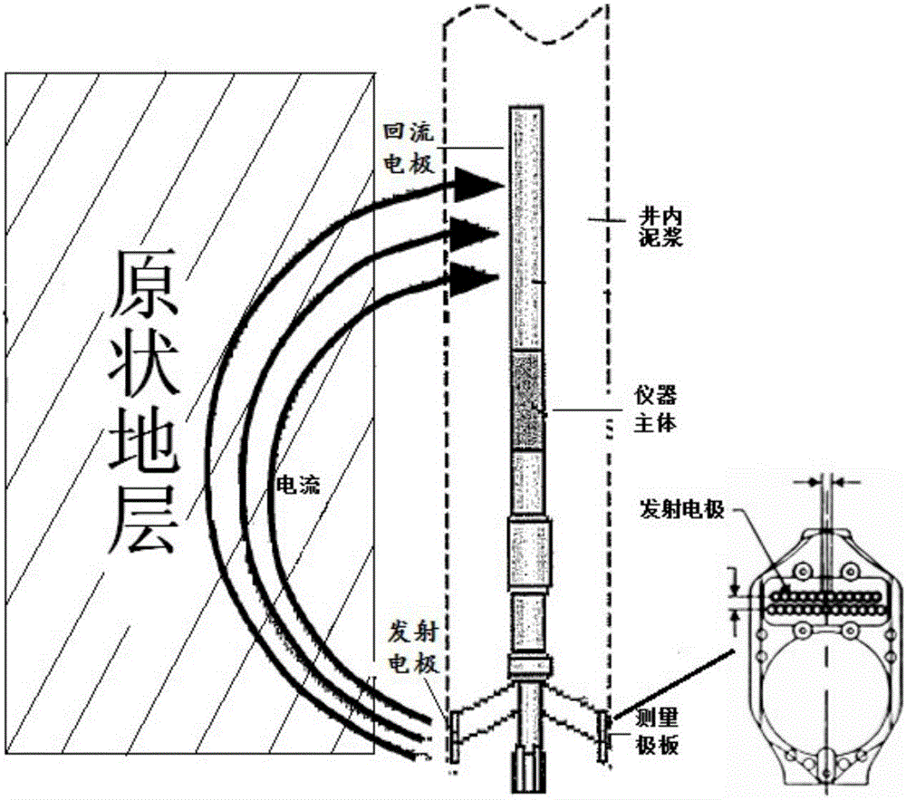
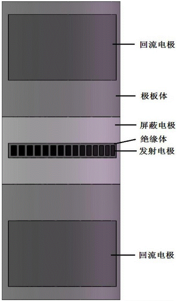
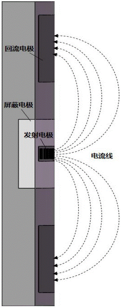
[0050] figure 2 It is the plate structure diagram of the instrument in the embodiment of the present invention, which shows the distribution position and arrangement of each electrode. The pole plate includes a group of emitter electrodes installed on the outer surface of the pole plate, and the emitter electrodes are arranged in a row and evenly distributed in the center of the pole plate. The polar plate also includes an integral shielding electrode, which is distributed around the emitter electrode and separated from the emitter electrode by an insulator. The shielding electrode is roughly flush with the outer surface of the emitting electrode, and the shielding electrode is made of a conductive material, which focuses the emitting current. The pole plate also includes an integral insulator, and the insulator is distributed between the shielding electrode and the emitting electrode, and plays an insulating and separating role on the emitting electrode and the shielding el...


PUM


Abstract

The invention relates to an electrical imaging well measuring device with emitting and reflowing inside an electrode plate and method. The device comprises the electrode plate, emitting electrodes, bucking electrodes and two reflowing electrodes. The electrode plate is used for clinging to the surface of the measured well wall and serving as a carrier of the emitting electrodes, the bucking electrodes, the reflowing electrodes and an insulator. The emitting electrodes are used for emitting currents to a stratum. The bucking electrodes are distributed around the emitting electrodes and play a role in focusing on current emitting. The two reflowing electrodes are symmetrically arranged at the two ends of the electrode plate and play a role in current reflowing. The device further comprises a current measuring device used for measuring the current changes of the emitting electrodes, a high-frequency alternating current power supply used for supplying high-frequency alternating currents to the emitting electrodes and a signal processing device used for generating a well wall imaging picture. The measuring device can measure the well wall more accurately and with higher resolution.

Description

technical field [0001] The invention relates to the technical field of petroleum well logging, in particular to a device and method for realizing high-resolution and high-accuracy measurement of the well wall in an oil-based mud environment. Background technique [0002] Electrical imaging logging was first applied in North Sea oilfields in Europe by Schlumberger in the 1980s. Electrical imaging logging data does not process the data into logging curves, but directly turns the data into visual images reflecting geological phenomena, which can more intuitively reflect geological characteristics and make the application easier. Electrical imaging logging has a high vertical resolution, can continuously reveal the detailed characteristics of the rock structure on the surface of the wellbore, and has directionality, and has the ability to accurately analyze the formation dip angle, azimuth and contact relationship between formations. [0003] With the in-depth development of ge...

Claims


Application Information

Patent Timeline
Patent Type & Authority Applications(China)
IPC IPC(8): E21B49/00
CPCE21B49/00
Inventor 张中庆
Owner HANGZHOU SUMAY TECH
Learn More