
Robot self-propelled chassis

A self-propelled, robotic technology, used in motor vehicles, vehicle maintenance, lifting vehicle accessories, etc., to achieve the effect of enhancing stability and ensuring safety and stability

Inactive Publication Date: 2017-06-13
CHINA AGRI UNIV
View PDF7 Cites 5 Cited by
  • Summary
  • Abstract
  • Description
  • Claims
  • Application Information

AI Technical Summary

Problems solved by technology

[0006] The purpose of the present invention is to provide a robot self-propelled chassis that solves the problem of flexible movement of the handling robot in the train compartment and the stability of the robot when it is working, improves the efficiency of loading and unloading, and realizes the mechanization and automation of agricultural materials loading and unloading

Method used


Image

  • Robot self-propelled chassis
  • Robot self-propelled chassis
  • Robot self-propelled chassis

Examples


Embodiment Construction

[0042] The specific implementation manners of the present invention will be further described in detail below in conjunction with the accompanying drawings and embodiments.

[0043] Robotic self-propelled chassis, used in conjunction with the robot. In the embodiment of the present invention, the self-propelled chassis of the robot is used in conjunction with the handling robot in the train compartment for loading, unloading and stacking bagged materials.

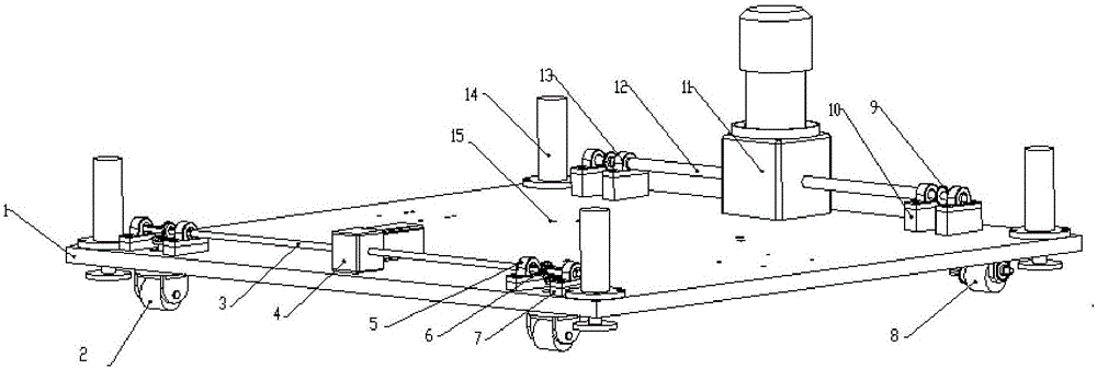
[0044] like figure 1 As shown, the robot self-propelled chassis includes: chassis 1, connecting mechanism 15, front axle steering system, rear axle drive system and hydraulic lifting system.

[0045] The connection mechanism 15 is arranged on the chassis 1 , and the handling robot is connected to the chassis 1 through the connection mechanism 15 .

[0046] The front axle steering system is arranged at the front of the chassis 1, and the front axle steering system includes a steering stepper motor-reducer group 4, a front ...


PUM


Abstract

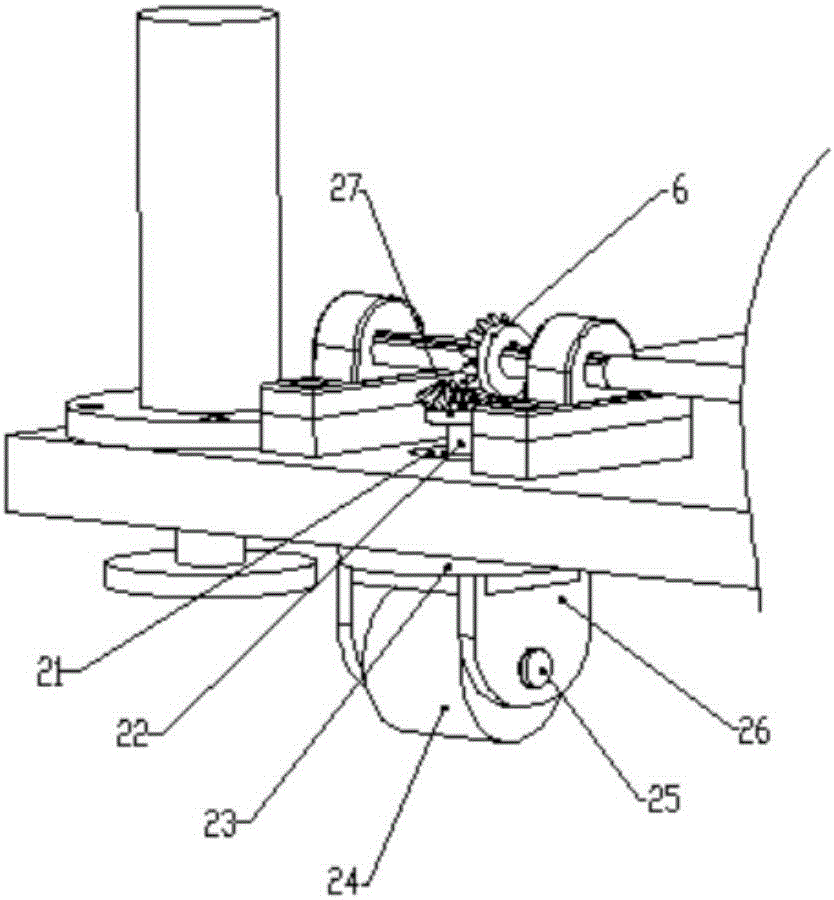
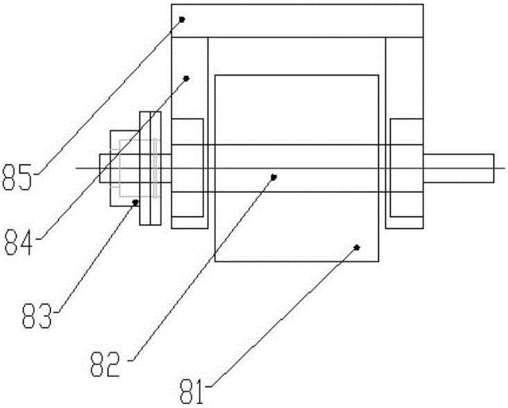
The invention belongs to the field of industrial automation, and particularly relates to a robot self-propelled chassis. The robot self-propelled chassis comprises a chassis (1), a connecting mechanism (15), a front axle steering system, a rear axle steering system and a hydraulic lifting system, wherein the connecting mechanism (15) is arranged on the chassis (1); the front axle steering system is arranged on the front part of the chassis (1), and comprises a steering stepping motor-reducer group (4), a front axle (3), a steering system bearing (5), a front axle bevel gear (6) and a steering wheel system (2); the rear axle steering system is arranged on the rear part of the chassis (1), and comprises a driving motor-reducer group (12), a rear axle (12), a driving system bearing (13), a rear axle chain wheel (9) and a driving wheel system (8); the hydraulic lifting system comprises a hydraulic cylinder (14), a hydraulic oil source system, a synchronous valve and a hydraulic pipeline; and the hydraulic cylinder (14), the hydraulic oil source system and the synchronous valve are communicated through the hydraulic pipeline.

Description

technical field [0001] The invention belongs to the field of industrial automation, in particular to a robot self-propelled chassis. Background technique [0002] At present, the warehouse handling and loading and unloading methods of bagged materials in my country are mainly carried by shoulders and pulled by trolleys. The loading and unloading workers are not only labor-intensive and low-efficiency, but also work in a dusty environment, which is easy to endanger physical and mental health. The handling robot equipment widely used for loading and unloading bagged materials at home and abroad is fixed on the assembly line or arranged on the moving guide rail, which cannot enter the train carriage or move flexibly to quickly grab the densely stacked bagged materials in the train carriage and loading and unloading. [0003] To sum up, the handling robots in the prior art are not suitable for the loading and unloading of densely stacked bagged materials in the train carriages,...

Claims


Application Information

Patent Timeline
Patent Type & Authority Applications(China)
IPC IPC(8): B62D63/04B60S9/10
CPCB60S9/10B62D63/04
Inventor 迟瑞娟李涵杜岳峰毛恩荣岳稳准
Owner CHINA AGRI UNIV
Learn More