Energy-saving heat exchanger for production of foamed plastic

An energy-saving heat exchanger and foam plastic technology, applied in the field of foam plastic production, can solve the problems of poor foaming effect of EPS raw material particles, rough surface of foam plastic products, lowering the temperature of foam plastic molds, etc., so as to avoid heat volatilization in vain, The effect of shortening working time and reducing heat

Inactive Publication Date: 2017-06-06
高密市美佳硕机械科技有限公司
View PDF0 Cites 0 Cited by
  • Summary
  • Abstract
  • Description
  • Claims
  • Application Information

AI Technical Summary

Problems solved by technology

[0003] The following problems exist in the prior art: 1. Air at room temperature is used in the air transportation pipeline. When using room temperature air to blow the EPS raw material particles into the mold cavity of the foam plastic mold, the room temperature air will quickly reduce the foam The temperature of the plastic mold will consume more heat in the subsequent process of using high-temperature steam to heat the foam plastic mold to heat the foam plastic mold to the target temperature, and the heating process will take longer; 2. Using cooling After the water cools the foam plastic mold, water with a higher temperature will be produced, and the water with a higher temperature will flow back to the cooling pool for cooling to be recycled. The heat of the water with a higher temperature is not only wasted, but also needs to be Only by using cooling towers to accelerate heat dissipation can the purpose of recycling be met; three, due to the long time of high-temperature steam heating the foam plastic mold in the prior art, the foaming effect of the EPS raw material particles in the foam plastic mold is poor, resulting in The surface of foam plastic products is not smooth, which seriously affects the quality of foam plastic products

Method used


Image

  • Energy-saving heat exchanger for production of foamed plastic
  • Energy-saving heat exchanger for production of foamed plastic

Examples


Embodiment Construction

[0016] In order to facilitate the understanding of those skilled in the art, the present invention will be further described below in conjunction with the accompanying drawings.

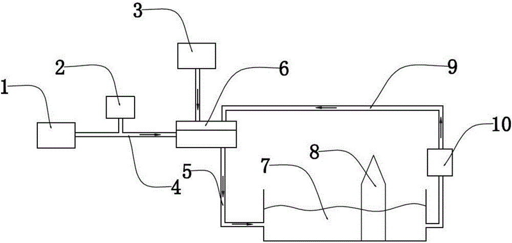
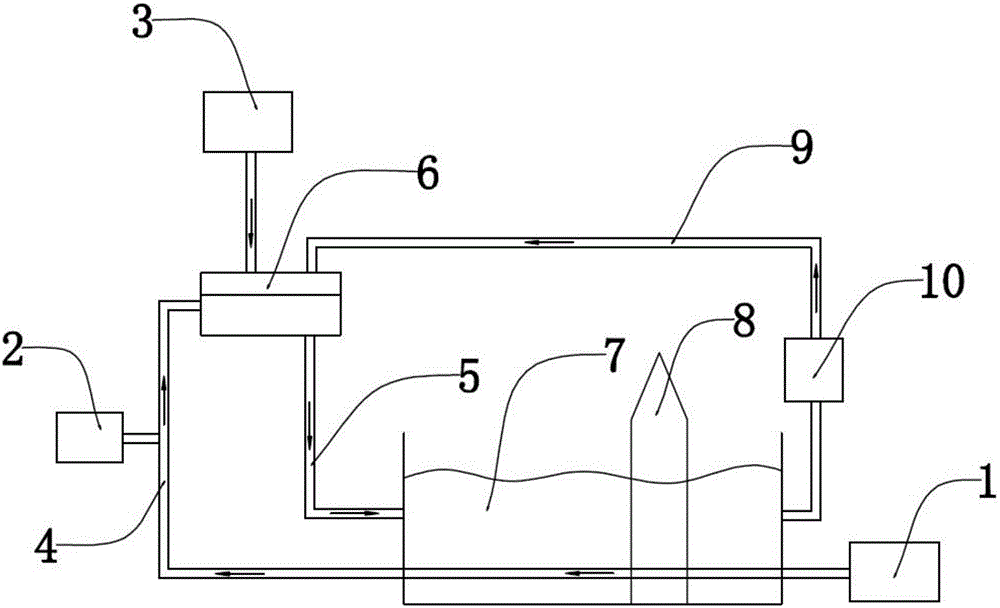
[0017] figure 2 It is a schematic diagram of the overall structure of the present invention, comprising a foam particle warehouse 2, a foam plastic mold 6, a high-temperature steam tank 3 and a cooling pool 7, and an air duct 4 is provided between the foam particle warehouse 2 and the foam plastic mold 6 to connect, and the high-temperature steam tank 3 Pipelines are provided between the foam plastic mold 6 to connect, the cooling pool 7 and the foam plastic mold 6 are respectively provided with water inlet pipes 9 and water outlet pipes 5 to connect, and part of the air pipes 4 are located in the cooling pool 7; the ends of the air pipes 4 A fan 1 is provided; a cooling tower 8 is provided in the cooling pool 7; a water pump 10 is provided on the water inlet pipe 9.

[0018] Concrete mode of work ...


PUM


Abstract

The invention discloses an energy-saving heat exchanger for the production of foamed plastic, and belongs to the technical field of the production of foamed plastic. The energy-saving heat exchanger comprises a foam grain bin, a foamed plastic die, a high-temperature steam tank and a cooling tank, wherein an air pipe is arranged between the foam grain bin and the foamed plastic die, so as to be connected between the foam grain bin and the foamed plastic die; a pipeline is arranged between the high-temperature steam tank and the foamed plastic die, so as to be connected between the high-temperature steam tank and the foamed plastic die; a water inlet pipe and a water outlet pipe are respectively arranged between the cooling tank and the foamed plastic die, so as to be connected between the cooling tank and the foamed plastic die; part of the air pipe is arranged in the cooling tank. The energy-saving heat exchanger has the advantages that as part of the air pipe is arranged in the cooling tank, air in the air pipe and high-temperature water in the cooling tank can perform heat exchange, the temperature of the air in the air pipe is increased, so that when EPS material grains are conveyed into the cavity in the foamed plastic die through air, the temperature in the foamed plastic die is slowly reduced, consumed heat during the process of subsequent heating the foamed plastic die through high-temperature steam is reduced, the foaming time is shortened, and the quality of foamed plastic products is improved.

Description

technical field [0001] The invention relates to the technical field of foam plastic production, in particular to an energy-saving heat exchanger for foam plastic production. Background technique [0002] Foam plastic products have the characteristics of light weight and good shock resistance, and are widely used in medical, food, electromechanical, instrumentation, hardware and daily product packaging. Foam plastic products are made of EPS (expandable polystyrene) raw material particles. become. Existing foam processing methods are (such as figure 1 Shown): The EPS raw material particles are put into the mold cavity of the foam plastic mold by means of air transport, and the foam plastic mold is heated by high-temperature steam to make the EPS raw material particles foam. After the foaming is completed, the foam plastic mold is cooled with cooling water , to separate the foamed plastic product from the foamed plastic mold. [0003] In the prior art, there are the followin...

Claims


Application Information

Patent Timeline
Patent Type & Authority Applications(China)
IPC IPC(8): B29C44/34
CPCB29C44/3419
Inventor 刘宝清
Owner 高密市美佳硕机械科技有限公司
Why Eureka
Try Eureka