
Ultra-wideband strong-coupling array antenna

An array antenna and strong coupling technology, which is applied in the field of microwave wireless communication, can solve the problems of limiting the minimum operating frequency of the unit antenna, the limitation of the lateral size of the antenna unit, and the inability to achieve effective radiation, so as to improve the antenna impedance broadband and wide-angle matching The effect of stable characteristics and transmission characteristics

Inactive Publication Date: 2017-05-31
NO 27 RES INST CHINA ELECTRONICS TECH GRP
View PDF4 Cites 16 Cited by
  • Summary
  • Abstract
  • Description
  • Claims
  • Application Information

AI Technical Summary

Problems solved by technology

[0006] (2) Theoretically, a frequency-invariant antenna with a self-similar structure has infinite bandwidth, but limited by the unit size and feed structure, the impedance broadband that can be realized is also limited, especially in the array environment, the lateral size of the antenna unit is limited by limit, which also limits the minimum operating frequency of the unit antenna;
[0007] (3) In order to achieve directional radiation and increase the gain of the array antenna, it is necessary to install a ground plate at the bottom of the antenna array. When the distance between the antenna unit and the ground plate is 1 / 4 wavelength of the operating frequency, the excitation current and the mirror current are superimposed in phase. However, when the distance from the ground plane is half a wavelength, the excitation current and the mirror current cancel out in phase, and effective radiation cannot be achieved. Therefore, the ground plane becomes another important factor that limits the working bandwidth of the array antenna.
[0008] To sum up, the antenna bandwidth of the traditional array is very limited, generally no more than 6 octaves, and the existing phased array antennas have not solved this problem

Method used


Image

  • Ultra-wideband strong-coupling array antenna
  • Ultra-wideband strong-coupling array antenna
  • Ultra-wideband strong-coupling array antenna

Examples


Embodiment Construction

[0027] The technical solutions of the present invention will be described clearly and completely below in conjunction with the accompanying drawings. Obviously, the described embodiments are only part of the embodiments of the present invention, rather than all the embodiments. Based on the embodiments of the present invention, all other embodiments obtained by those of ordinary skill in the art without creative work shall fall within the protection scope of the present invention.

[0028] In the description of the present invention, it should be noted that the orientation or positional relationship indicated by the terms "upper", "lower", "front" and "rear" is based on the positional relationship shown in the drawings, and is only for convenience The content of the present invention is described instead of implying that the referred elements must be arranged in a specific orientation, and therefore cannot be understood as a limitation to the present invention.

[0029] In addition...


PUM

PropertyMeasurementUnit
Thicknessaaaaaaaaaa
Lengthaaaaaaaaaa
Thicknessaaaaaaaaaa

Abstract

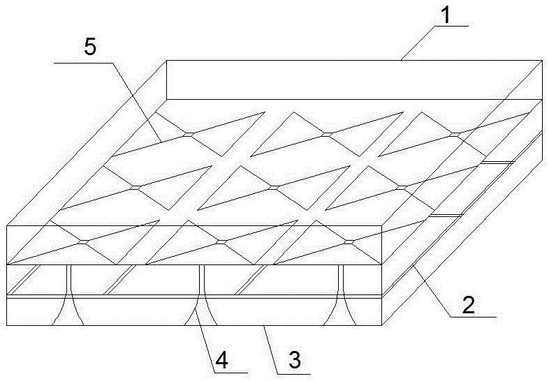
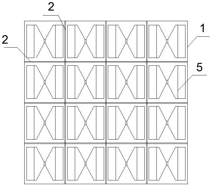
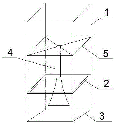
The invention discloses an ultra-wideband strong-coupling array antenna. The array antenna comprises a plurality of antenna units arranged in an array. Each antenna unit includes a dipole antenna array element, a tapered Balun converter, and a resistive frequency selection surface, wherein the dipole antenna array element is a bowtie-shaped short dipole antenna, the resistive frequency selection surface is arranged below the dipole antenna and shaped as a square ring, the tapered Balun converter is arranged below the dipole antenna array element and passes through the resistive frequency selection surface, and the output end of the tapered Balun converter is connected with the port of the dipole antenna. A metal ground plate is arranged below the antenna units. The array antenna can break through the restriction of the grating lobe condition, the unit size and the metal ground plate on the array performance, can work normally in a larger broadband scope, and can meet the functional requirements of different platforms and different tasks.

Description

Technical field [0001] The invention relates to the technical field of microwave wireless communication, in particular to an ultra-wideband strongly coupled array antenna. Background technique [0002] With the rapid development of wireless communication technology, higher and higher requirements are put forward for various antennas. On the one hand, the rise of indoor high-speed wireless data access technology has put forward a wide range of needs for ultra-wideband antennas. On the other hand, due to the working frequency range of the ultra-wideband communication system, there are also such things as wireless local area network and global microwave interconnection. In communication systems, in order to reduce the mutual interference between different communication systems, broadband phased array antennas have been increasingly used. [0003] Modern phased array antennas use an electronic system to control the feed amplitude and phase of each unit in the antenna array so that the...

Claims


Application Information

Patent Timeline
IPC IPC(8): H01Q1/50H01Q21/00
CPCH01Q1/50H01Q21/00
Inventor 马骥薛东海朱杰
Owner NO 27 RES INST CHINA ELECTRONICS TECH GRP
Learn More