Auxiliary interconnection in special-shaped arcs Silver-gated oblique hooks Cathode structure light-emitting display with concave tire surface

A technology of a light-emitting display and a cathode structure, which is applied in the fields of science and technology and the intersection of vacuum science and technology, and can solve the problems of inability to adapt to the market demand of display technology, failure of field emission light-emitting displays, and vulnerability to damage and pollution.

Active Publication Date: 2018-01-30
阜阳市战千里知识产权运营有限公司
View PDF6 Cites 0 Cited by
  • Summary
  • Abstract
  • Description
  • Claims
  • Application Information

AI Technical Summary

Problems solved by technology

Second, the integrated fabrication of carbon nanotube cathodes and gates
When making the subsequent structure, it is easy to cause damage to the previous structure; in addition, the carbon nanotube layer is thin-layered, which is very easy to be damaged and polluted, so it is necessary to integrate the two structures of the carbon nanotube cathode and gate production, the degree of their mutual influence must be reduced, or the mutual influence between the two must be completely eliminated
Once the carbon nanotube layer is damaged or polluted, the ability to emit electrons decreases, which will cause a complete failure of the field emission display.
Third, the production of carbon nanotube layers
In addition, the production cost of the field emission light-emitting display is also one of the things that must be taken into account
Too expensive field emission luminescent displays cannot meet the actual product needs of the display technology market

Method used


Image

  • Auxiliary interconnection in special-shaped arcs Silver-gated oblique hooks Cathode structure light-emitting display with concave tire surface
  • Auxiliary interconnection in special-shaped arcs Silver-gated oblique hooks Cathode structure light-emitting display with concave tire surface
  • Auxiliary interconnection in special-shaped arcs Silver-gated oblique hooks Cathode structure light-emitting display with concave tire surface

Examples


Embodiment Construction

[0050] The present invention will be further described below in conjunction with the accompanying drawings and embodiments, but the present invention is not limited to this embodiment.

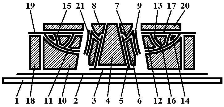
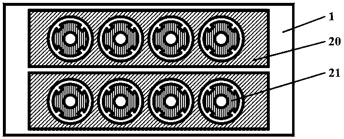
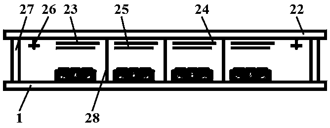
[0051] The light-emitting display of the special-shaped arc internal auxiliary interconnection silver-gated oblique hook concave tire surface cathode structure in this embodiment is as follows: figure 1 , figure 2 and image 3 As shown, it includes a vacuum chamber composed of an upper compression-resistant flat white glass cover plate 22, a lower compression-resistant flat white glass cover plate 1 and a transparent glass frame 27; an anodic oxide transparent square film is arranged on the upper compression-resistant flat white glass cover plate 22 Layer 23, the anode extended wide curved silver layer 24 connected to the anodic oxide transparent square film layer 23 and the phosphor layer 25 prepared on the anodic oxide transparent square film layer 23; Auxiliary interconnection within the...


PUM


Abstract

The invention relates to a light-emitting display with a special-shaped arc internal auxiliary interconnect silver gate control oblique hook concave tread cathode structure. The light-emitting display comprises a vacuum chamber formed by an upper compressive flat white glass cover plate, a lower compressive flat white glass cover plate and a transparent glass frame, wherein the upper compressive flat white glass cover plate is provided with an anodic oxide transparent square film layer, an anode extending wide-curved silver layer connected with the anodic oxide transparent square film layer, and a fluorescent powder layer prepared on the anodic oxide transparent square film layer; the special-shaped arc internal auxiliary interconnect silver gate control oblique hook concave tread cathode structure is arranged on the lower compressive flat white glass cover plate; and a getter and a hidden support column auxiliary component are arranged in the vacuum chamber. The light-emitting display has the advantages of being excellent in light-emitting brightness adjustability, stable in manufacturing process, high in brightness, short in response time and high in anode current.

Description

technical field [0001] The present invention belongs to the fields of display technology, nanometer science and technology, optoelectronic science and technology, microelectronics science and technology, integrated circuit science and technology, and vacuum science and technology, and relates to a flat field emission display The manufacture specifically relates to the manufacture of a planar field emission luminescent display of a carbon nanotube cathode, and particularly relates to a display and a manufacturing process of a luminescent display with an auxiliary interconnected silver-gated oblique hook concave tread cathode structure in a special-shaped arc. Background technique [0002] Carbon nanotubes are a very good source of cold cathode electrons. In a vacuum environment, they can continuously provide cathode electrons for the field emission luminescence display in the form of "field emission", thus forming the necessary conditions for the normal operation of the field ...

Claims


Application Information

Patent Timeline
Patent Type & Authority Patents(China)
IPC IPC(8): H01J31/12H01J29/04H01J9/02
CPCH01J9/02H01J29/04H01J31/12
Inventor 李玉魁高宝宁
Owner 阜阳市战千里知识产权运营有限公司
Why Eureka
Try Eureka