
Circuit and method for detecting inductance breaking arc maintenance time by signal phase separation

A technology for maintaining time and circuits, applied in the direction of testing circuits, measuring electricity, measuring electrical variables, etc., can solve the problems of time interval errors, counting deviations, and the inability to accurately detect the end time of breaking arc discharge, etc.

Inactive Publication Date: 2019-06-18
XIAN UNIV OF SCI & TECH
View PDF18 Cites 0 Cited by
  • Summary
  • Abstract
  • Description
  • Claims
  • Application Information

AI Technical Summary

Problems solved by technology

Using method ②, its working principle is simple and easy to apply, but due to many factors, there may be errors in the time interval between two open circuit sparks, which will cause deviations in counting
[0004] In order to solve the above problems, the Chinese patent application number 201611261074.6 discloses a circuit and method for detecting the time of inductive circuit breaking arc discharge. However, according to the breaking arc discharge characteristic curve of the small inductance inductive circuit, when the inductance is small, the breaking arc discharge voltage has been rising, and there is no obvious second sudden rise phenomenon, so for small For the breaking arc discharge of inductance, the patented circuit and method with application number 201611261074.6 cannot accurately detect the end time of the breaking arc discharge

Method used


Image

  • Circuit and method for detecting inductance breaking arc maintenance time by signal phase separation
  • Circuit and method for detecting inductance breaking arc maintenance time by signal phase separation
  • Circuit and method for detecting inductance breaking arc maintenance time by signal phase separation

Examples


Embodiment Construction

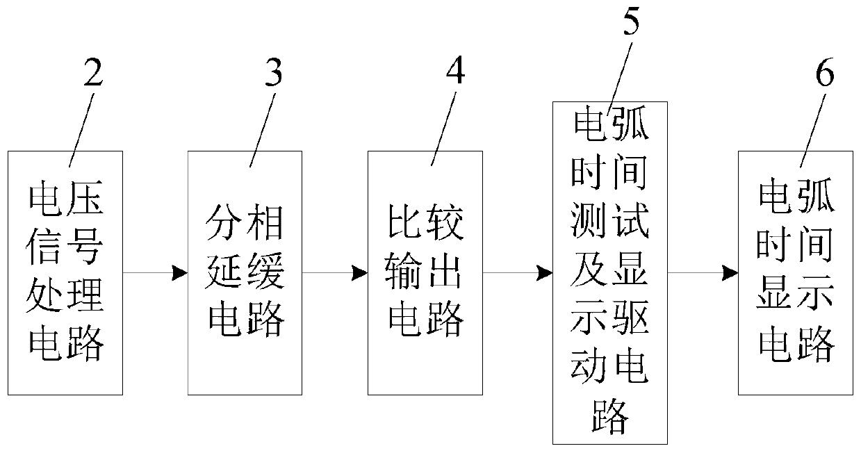
[0042] Such as figure 1 As shown, the circuit of the present invention that uses signal phase separation to detect inductance breaking arc maintenance time includes a voltage signal processing circuit 2, a phase separation delay circuit 3, a comparison output circuit 4, an arc time test and display drive circuit 5 and an arc connected in sequence. Time display circuit 6;

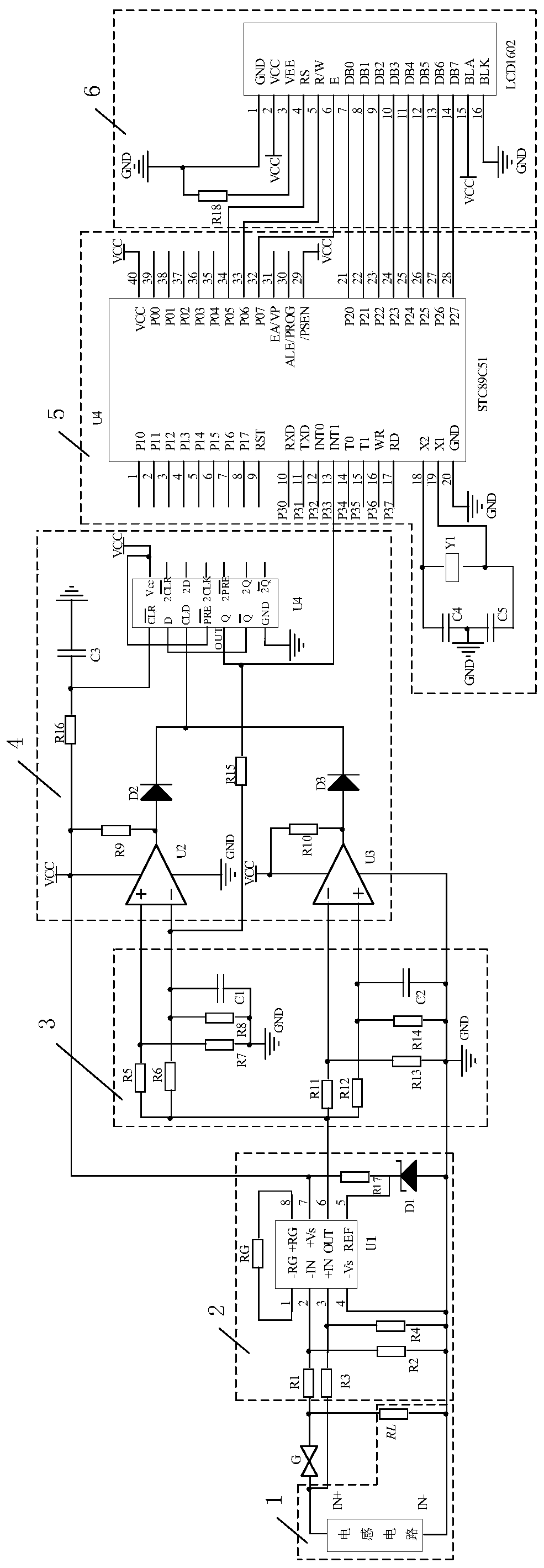
[0043] Such as image 3 As shown, the voltage signal processing circuit 2 includes an instrumentation amplifier U1, a resistor R1, a resistor R2, a resistor R3, a resistor R4, a resistor R17 and a Zener diode D1, and one end of the resistor R1 is a sampler of the voltage signal processing circuit 2. Point negative voltage input terminal VIN-, one end of the resistor R3 is the positive voltage input terminal VIN+ of the sampling point of the voltage signal processing circuit 2, and the negative voltage input terminal VIN- of the sampling point is a voltage dividing resistor composed of series connected resis...


PUM


Abstract

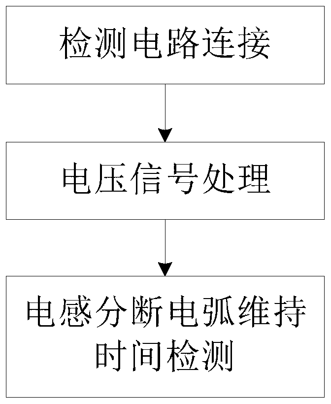
The invention discloses a circuit and method for detecting the maintenance time of inductance breaking arc by signal phase separation. The circuit includes a voltage signal processing circuit, a phase separation delay circuit, a comparison output circuit, an arc time test and display driving circuit and an arc connected in sequence. Time display circuit; the phase delay circuit includes a first phase delay circuit and a second phase delay circuit, the first phase delay circuit includes a capacitor C1, a first proportional resistance network and a second proportional resistance network; the second phase delay The circuit includes a capacitor C2, a third proportional resistance network and a fourth proportional resistance network; the method comprises the steps of: 1. detection circuit connection, 2. voltage signal processing, 3. detection of inductance breaking arc maintenance time. The invention has the advantages of simple circuit structure, reasonable design, convenient implementation, low cost, stable and reliable operation, fast and effective detection of inductance breaking arc maintenance time, wide application range, strong practicability, and good popularization and application value.

Description

technical field [0001] The invention belongs to the technical field of detecting the maintenance time of an inductance breaking arc, and in particular relates to a circuit and a method for detecting the maintenance time of an inductance breaking arc by using signal phase separation. Background technique [0002] The safety spark test device is the basic equipment for studying the intrinsically safe performance of circuits, and various ignition curves drawn according to the test results obtained on the device are the basis for designing intrinsically safe circuits. Use the safety spark test device to test the inductive circuit. The discharge time is the duration of the circuit current decaying from the steady state value before disconnection to zero when detonated. It depends on the material, structure, switching speed of the device electrode and the characteristics of the circuit transition process. And test gas concentration, temperature, pressure, etc. If it is possible t...

Claims


Application Information

Patent Timeline
Patent Type & Authority Patents(China)
IPC IPC(8): G01R31/14G01R31/12
CPCG01R31/1227G01R31/14
Inventor 刘树林李青青张琼赵亚娟黄治王肖
Owner XIAN UNIV OF SCI & TECH
Learn More