LED lamp with radiator

A technology of LED lamps and heat sinks, which is applied to components of lighting devices, lighting devices, cooling/heating devices of lighting devices, etc., can solve problems such as low heat dissipation efficiency, temperature rise, and influence of lamps, and increase the heat exchange area , improve stability, improve the effect of cooling efficiency

Inactive Publication Date: 2017-05-31
佛山勤顺科技有限公司
View PDF9 Cites 7 Cited by
  • Summary
  • Abstract
  • Description
  • Claims
  • Application Information

AI Technical Summary

Problems solved by technology

In this solution, an axial flow fan is built between the lamp holder and the heated lamp bead circuit board assembly. The fan starts to make the air convect up and down, and accelerates the release of internal heat, in order to solve the technical problem of low heat dissipation efficiency in the existing technology
However, it cannot be used for ceiling lighting purposes. The reason is that the air started by the fan is convected from top to bottom, and the design of the ceiling is that the parts above the ceiling are generally sealed, and generally there is no air flow. The cooling effect It is not good in itself. If the LED lamp adopts the form of downward air intake, then the heat will be brought to the interior of the ceiling, causing the temperature to rise rapidly, which will directly affect other lamps; if the LED lamp adopts the form of upward air intake, due to The air in the ceiling is thin, and the fan of the LED lamp will be damaged after working for a period of time, and the cooling function cannot be implemented. Currently, it is only suitable to use LED bulbs with a maximum power of 60-70W

Method used


Image

  • LED lamp with radiator

Examples


Embodiment Construction

[0016] The technical solution will be described in detail below in conjunction with specific embodiments.

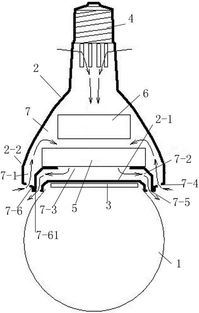
[0017] Such as figure 1 As shown, the present invention is an LED lamp with a heat dissipation device, which includes a bulb 1, a bulb holder assembly 2, an LED light source board 3 and a lamp holder 4, and the lamp holder 4 and the bulb holder 1 are respectively fixed on the bulb holder assembly 2 The bulb seat assembly 2 includes a base 2-1 fixedly connected to the bulb, a bulb seat cover 2-2 connected to the base, and a heat dissipation cavity for accommodating a cooling fan 5 and a power supply 6 is provided between the bulb seat cover and the base Body 7, the LED light source board is fixed on the base, the air inlet air duct 7-1 and the air outlet air duct 7-2 are arranged in the heat dissipation cavity, and there is a vent 7-3 between the air inlet air duct and the air outlet air duct, for heat dissipation The fan is arranged on the air vent to accelerate the gas...


PUM


Abstract

The invention discloses an LED lamp with a radiator. The LED lamp is characterized by comprising a bulb shell, a bulb shell seat assembly, an LED light source plate and a lamp head. The lamp head and the bulb shell are fixed to the bulb shell seat assembly. The bulb shell seat assembly comprises a base fixedly connected with the bulb shell, and a bulb shell seat outer cover connected with the base. A radiating cavity holding a radiating fan and a power source is arranged between the bulb shell seat outer cover and the base. The LED light source plate is fixed to the base. The radiating cavity is internally provided with an air inlet channel and an air outlet channel. A ventilation opening is formed between the air inlet channel and the air outlet channel. The radiating fan is arranged at the ventilation opening, and air flowing between the air inlet channel and the air outlet channel is accelerated. The end, toward the bulb shell, of the bulb shell seat outer cover is provided with a plurality of air inlets corresponding to the air inlet channel, and air outlets corresponding to the air outlet channel. The LED lamp is simple in structure and superior in performance compared with the same types of products.

Description

technical field [0001] The invention relates to the technical field of lighting, in particular to an LED lamp with a cooling device. Background technique [0002] LED=Light Emitting Diode, light emitting diode, is a solid-state semiconductor device that can convert electrical energy into visible light, and it can directly convert electricity into light. The design of living room lamps and lanterns in the 21st century is based on the design of LED lighting bulbs. At the same time, it fully embodies the development trend of energy-saving, healthy, artistic and humanized lighting, and has become the leading lighting culture of the living room. Traditional incandescent lamps (tungsten filament lamps) have high energy consumption and short lifespan. Under the environment of global resource shortage, their production has been gradually banned by governments of various countries. The replacement products are electronic energy-saving lamps. Although electronic energy-saving lamps ha...

Claims


Application Information

Patent Timeline
Patent Type & Authority Applications(China)
IPC IPC(8): F21K9/232F21V29/67F21V19/00F21Y115/10
CPCF21V29/67F21V19/003
Inventor 宁勤顺
Owner 佛山勤顺科技有限公司
Why Eureka
Try Eureka