Eureka AIR delivers breakthrough ideas for toughest innovation challenges, trusted by R&D personnel around the world.

Rotary device and gas separating device

One kind of rotating device and another kind of technology are applied in the direction of valve device, separation method, and dispersed particle separation, which can solve the problems of complicated control pipelines and control valves, high equipment processing costs, etc., to achieve automatic control, reduce manufacturing costs and Effect of occupying space and reducing production cost

Active Publication Date: 2017-05-31
CHENGDU SEPMEM SCI & TECH
View PDF11 Cites 15 Cited by
  • Summary
  • Abstract
  • Description
  • Claims
  • Application Information

AI Technical Summary

Problems solved by technology

[0003] The purpose of the present invention is to provide a rotating device, aiming to improve the problem of complicated control pipelines and control valves and high equipment processing costs in the multi-pipeline process

Method used


Image

  • Rotary device and gas separating device
  • Rotary device and gas separating device
  • Rotary device and gas separating device

Examples


Embodiment Construction

[0024] In order to make the purpose, technical solutions and advantages of the embodiments of the present invention clearer, the technical solutions in the embodiments of the present invention will be clearly and completely described below in conjunction with the accompanying drawings in the embodiments of the present invention. Obviously, the described embodiments It is some embodiments of the present invention, but not all of them. Based on the implementation manners in the present invention, all other implementation manners obtained by persons of ordinary skill in the art without creative efforts fall within the protection scope of the present invention. Accordingly, the following detailed description of the embodiments of the invention provided in the accompanying drawings is not intended to limit the scope of the claimed invention, but merely represents selected embodiments of the invention. Based on the implementation manners in the present invention, all other implement...


PUM


Abstract

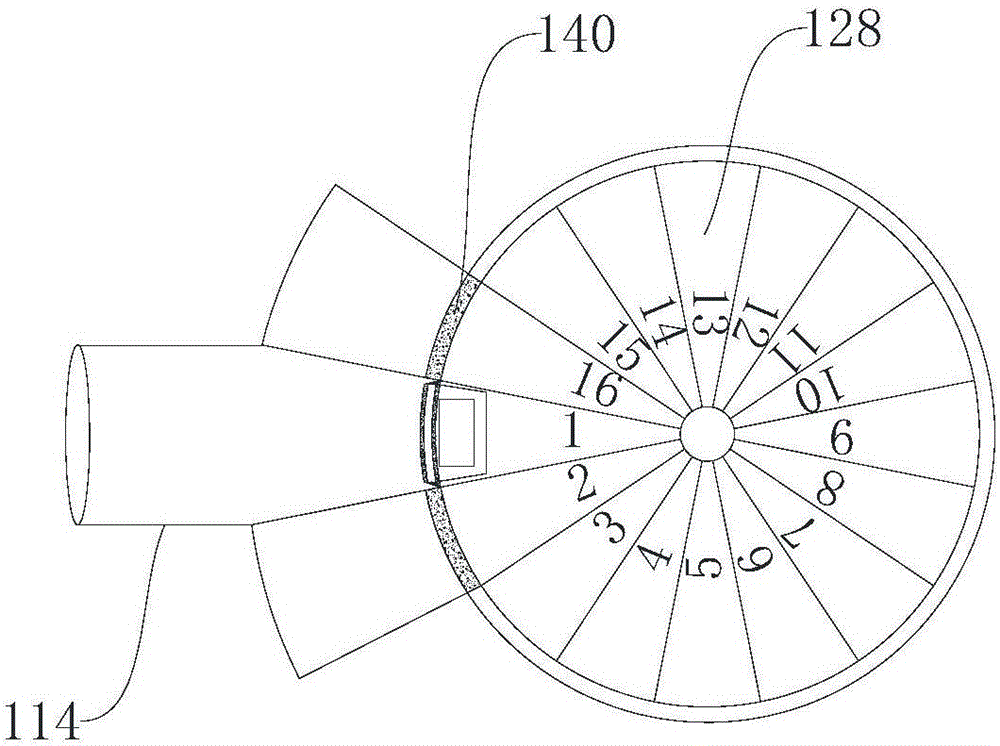
The invention provides a rotary device and a gas separating device and relates to the field of mechanical equipment. The rotary device comprises a rotating component and a non-rotating component, and the non-rotating component is arranged on the rotating component in a sleeving mode. A plurality of first runners communicating with an outer pipeline are formed in the non-rotating component, a plurality of second runners matched with the multiple first runners are formed in the rotating component, and a communicating pipe net is formed among the multiple first runners and the multiple second runners. The rotating component has a plurality of rotating states, and when the rotating component is moved to another rotating state from a rotating state, the multiple first runner and the multiple second runners are transformed into another communicating state from a communicating state. According to the rotary device and the gas separating device, the effect that an intricate control valve in the multi-pipeline technological process is replaced by one single rotary device can be achieved, and machining cost of equipment is reduced. The gas separating device comprises the rotary device, and manufacturing cost and the occupied space of multi-pipeline equipment in the gas separating device are reduced.

Description

technical field [0001] The invention relates to the field of mechanical equipment, in particular to a rotating device and a gas separation device. Background technique [0002] At present, many chemical production processes involve multi-pipeline control, such as gas pressure swing adsorption or gas temperature swing adsorption, which involve multiple pipelines and multiple control valves. Complicated control pipelines and control valves are not convenient for automatic control, and increase the processing consumables of the equipment and increase the production cost. Contents of the invention [0003] The object of the present invention is to provide a rotating device, aiming at improving the problems of intricate control pipelines and control valves and high equipment processing costs in the multi-pipeline process. [0004] Another object of the present invention is to provide a gas separation device, which includes the above-mentioned rotating device, which reduces the...

Claims


Application Information

Patent Timeline
Patent Type & Authority Applications(China)
IPC IPC(8): F16K11/10B01D53/047
CPCB01D53/0462B01D53/047F16K11/10
Inventor 张惊涛宋强
Owner CHENGDU SEPMEM SCI & TECH
Why Eureka
Eureka Blog
Learn More