
Mechanical seal ring provided with multi-sawteeth-shaped spiral grooves

A technology of mechanical seals and spiral grooves, which is applied in the direction of engine seals, mechanical equipment, engine components, etc., can solve problems such as high leakage rate, limited fluid film carrying capacity, and insufficient fluid film rigidity, so as to improve the lubrication state and eliminate Potential safety hazards, the best effect of hydrodynamic pressure effect

Active Publication Date: 2017-05-31
云南流体规划研究院有限公司
View PDF8 Cites 3 Cited by
  • Summary
  • Abstract
  • Description
  • Claims
  • Application Information

AI Technical Summary

Problems solved by technology

When the moving ring rotates, the gas medium is pumped into the sealing end face by using the strong dynamic and static pressure effect of the dynamic pressure groove. The mechanical seal can maintain a non-contact operation under the condition of a micron-sized gas film, but the spiral groove mechanical seal widely used in the industry still has problems such as high leakage rate, limited bearing capacity of the fluid film and insufficient rigidity of the fluid film. , failure accidents occur from time to time

Method used


Image

  • Mechanical seal ring provided with multi-sawteeth-shaped spiral grooves
  • Mechanical seal ring provided with multi-sawteeth-shaped spiral grooves
  • Mechanical seal ring provided with multi-sawteeth-shaped spiral grooves

Examples


Embodiment 1

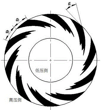
[0020] Such as figure 1 As shown, a mechanical seal ring with multiple zigzag spiral grooves, one side of the end face of the seal ring is the high pressure side, namely upstream, and the other side is the low pressure side, namely downstream, and there are 10 seal rings evenly distributed along the circumference of the end face The spiral groove opens on the high-pressure side of the end face, and the root of each spiral groove is sawtooth-shaped, and the number of sawtooth at the root of each spiral groove is 3; the ungrooved area of ​​the end face of the sealing ring forms a sealing dam, and the groove ratio (The ratio of the arc length of the outer circumference of the ungrooved area to the arc length of the outer circumference of the slotted area) a 2 / a 1 =1; groove depth is 5μm;

[0021] The outline of each helical groove is composed of logarithmic helixes with equal helix angles, and the helix angle α =15°.

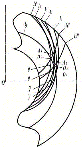
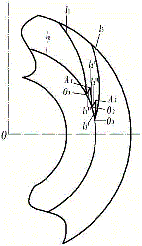
[0022] The construction process of a single multi-zi...

Embodiment 2

[0026] A mechanical seal ring with multiple zigzag spiral grooves. One side of the end face of the seal ring is the high pressure side, namely upstream, and the other side is the low pressure side, namely downstream. There are 20 spiral grooves evenly distributed along the circumference of the end face on the end face of the seal ring. , the spiral groove opens on the high-pressure side of the end face, the root of each spiral groove is sawtooth-shaped, and the number of sawtooth at the root of each spiral groove is 9; the ungrooved area of ​​the end face of the sealing ring forms a sealing dam, and the groove ratio (unopened) The ratio of the arc length of the outer circumference of the grooved area to the arc length of the outer circumference of the slotted area) a 2 / a 1 =1; groove depth is 30μm;

[0027] The outline of each helical groove is composed of logarithmic helixes with equal helix angles, and the helix angle α =30°.

[0028] The construction process of a sin...


PUM


Abstract

The invention relates to a mechanical seal ring provided with multi-sawteeth-shaped spiral grooves. The multiple spiral grooves evenly distributed along the circumference of the end face are formed in the end face of the seal ring, and the groove root of each spiral groove is in a sawtooth shape. According to the mechanical seal ring provided with the multi-sawteeth-shaped spiral grooves, the hydrodynamic effect of a fluid of the end face of the mechanical seal ring is reinforced, and the hydrodynamic effect generation range is increased, so that a stable fluid film is formed in the running process of the mechanical seal ring, the friction extent of the end face is reduced, and the service life is greatly prolonged.

Description

technical field [0001] The invention relates to a mechanical sealing ring with multiple zigzag spiral grooves, which belongs to the technical field of mechanical sealing, and is especially suitable for the end face sealing of shaft ends of various rotating machines such as pumps, compressors, and reaction kettles. Background technique [0002] Mechanical seals, such as dry gas seals for sealing gases and upstream pumping mechanical seals for sealing liquids, are widely used in medium and high-speed rotating machinery such as centrifugal compressors, fans, and reactors due to their unique performance advantages. The mechanical seal is to open a dynamic pressure groove with a spiral line, a straight line or an arc line on the sealing end surface. Among all kinds of dynamic pressure grooves, the spiral groove is the most typical. When the moving ring rotates, the gas medium is pumped into the sealing end face by using the strong dynamic and static pressure effect of the dynamic...

Claims


Application Information

Patent Timeline
Patent Type & Authority Applications(China)
IPC IPC(8): F16J15/16F16J15/40
CPCF16J15/162F16J15/164F16J15/406
Inventor 宋鹏云邓成香陈果
Owner 云南流体规划研究院有限公司
Learn More