
Reducer brake for crane

A technology of machine brakes and cranes, applied in the types of brakes, axial brakes, gear transmission mechanisms, etc., can solve problems such as the inability to achieve adjustable brake pressure, the large space for the axial size of the brake, and the inability to lock the brake with the opening pressure. , to achieve good dynamic and static sealing effect, simple structure, and the effect of ensuring braking performance

Inactive Publication Date: 2017-05-31
XCMG XUZHOU TRUCK MOUNTED CRANE
View PDF7 Cites 0 Cited by
  • Summary
  • Abstract
  • Description
  • Claims
  • Application Information

AI Technical Summary

Problems solved by technology

[0002] At present, when the crane reducer is working, it is often in a low-speed and heavy-load state, especially in an overload state, and the brake of the reducer is generally a normally closed brake. At the moment of starting and stopping, the brake needs to be opened and closed, and the brake is easy to withstand heavy loads. Large impact, in the prior art (CN203413005U-combined spring multi-friction disc rotary reducer brake) usually adopts two O-ring seals around the piston, and the O-ring is prone to wear and leakage during the axial movement of the piston. Leakage, the brake cannot be completely disengaged, causing abnormal noise of the reducer, and at the same time, due to manufacturing errors, the opening pressure of the brake is too large or too small, and the opening pressure is too small, which may cause the brake to not lock (due to the back pressure in the hydraulic system) , Excessive opening pressure may cause abnormal brake noise, and it is impossible to adjust the brake pressure
In addition, the crane reducer generally uses a cylindrical spring, resulting in a large space for the axial dimension of the brake

Method used


Image

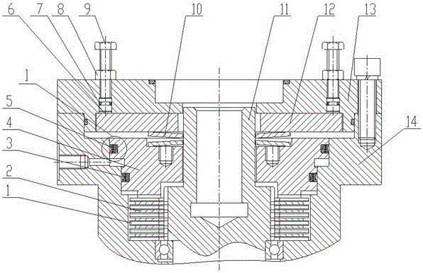
  • Reducer brake for crane
  • Reducer brake for crane

Examples


Embodiment Construction

[0017] The present invention will be further described below in conjunction with the accompanying drawings. The following examples are only used to illustrate the technical solution of the present invention more clearly, but not to limit the protection scope of the present invention.

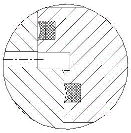
[0018] Such as figure 1 As shown, a reducer brake for a crane includes a friction static plate 1, a friction moving plate 2, a first combination seal 3, a piston 4, a second combination seal 5, multiple adjustment devices, a disc spring set 10, and a coupling 11. The pressure plate 12, the connecting plate 13 and the brake housing 14, the static friction plate 1 is located under the moving friction plate 2, the moving friction plate 2 is located under the piston 4, the static friction plate 1 and the The brake housing 14 is connected by an involute gear, the friction moving plate 2 and the coupling 11 are connected by an involute gear, and the first combined seal 3 and the second combined seal ...


PUM


Abstract

The invention discloses a reducer brake for a crane. The reducer brake comprises a friction static disc, a friction movable disc, a first combined seal, a piston, a second combined seal, adjusting devices, a spring device, a coupling, a pressure plate, a connecting plate, and a brake shell, wherein the friction static disc is located below the friction movable disc; the friction movable disc is located below the piston; the friction static disc is connected with gears of the brake shell; the friction movable disc is connected with gears of the coupling; the first combined seal and the second combined seal are distributed at the upper end and the lower end of the outer diameter of the piston; the spring device is located on the piston; the pressure plate is mounted in the connecting plate and is located on the spring device to press the spring device; the adjusting devices are mounted on the brake shell; and the lower ends of the adjusting devices are in contact with the pressure plate. The device has the characteristics of being small in friction coefficient, good in sealing effect, high in wear resistance, adjustable in braking torque of the brake, and smaller in axial spatial size.

Description

technical field [0001] The invention relates to a reducer brake for a crane, belonging to the technical field of reducer brake design. Background technique [0002] At present, when the crane reducer is working, it is often in a low-speed and heavy-load state, especially in an overload state, and the brake of the reducer is generally a normally closed brake. At the moment of starting and stopping, the brake needs to be opened and closed, and the brake is easy to withstand heavy loads. Large impact, in the prior art (CN203413005U-combined spring multi-friction plate rotary reducer brake) usually adopts two O-ring seals around the piston, and the O-ring is prone to wear and form leakage during the axial movement of the piston. Leakage, the brake cannot be completely disengaged, causing abnormal noise of the reducer, and at the same time, due to manufacturing errors, the opening pressure of the brake is too large or too small, and the opening pressure is too small, which may ca...

Claims


Application Information

Patent Timeline
Patent Type & Authority Applications(China)
IPC IPC(8): F16D55/226F16D121/04
CPCF16D55/226F16D2121/04
Inventor 陈志伟孔德强孔凡相周哲
Owner XCMG XUZHOU TRUCK MOUNTED CRANE
Learn More