
Roller bearing inner and outer ring roller path abrasion resisting structure and machining method thereof

A technology of roller bearing and processing method, applied in the direction of bearing components, shafts and bearings, mechanical equipment, etc., can solve the problems of not ensuring the reduction of roller bearing wear, affecting the strength and accuracy of the roller bearing, and the process is not easy to control, etc. Achieve excellent storage capacity, improved wear resistance and good effect

Active Publication Date: 2017-05-31
JIANGSU UNIV OF SCI & TECH
View PDF9 Cites 5 Cited by
  • Summary
  • Abstract
  • Description
  • Claims
  • Application Information

AI Technical Summary

Problems solved by technology

The ion implantation method will cause surface damage, which must be heated and annealed to restore stability, and the process is complicated
The roughness of the inner and outer rings of the roller bearings treated by the powerful shot peening method is relatively poor, and may affect the strength and precision of the roller bearings. At the same time, the process of strong shot peening is not easy to control
Although the surface film deposition method can improve the strength of cylindrical roller bearings, it cannot ensure that the wear of the roller bearings is reduced during the working process

Method used


Image

  • Roller bearing inner and outer ring roller path abrasion resisting structure and machining method thereof
  • Roller bearing inner and outer ring roller path abrasion resisting structure and machining method thereof
  • Roller bearing inner and outer ring roller path abrasion resisting structure and machining method thereof

Examples


Embodiment

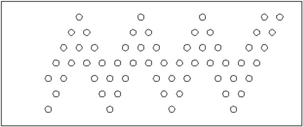
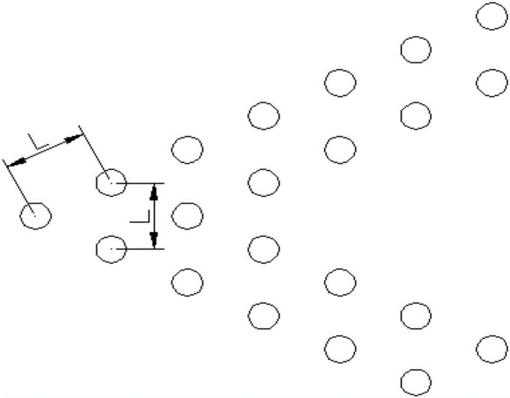
[0039] Embodiment: A wear-resistant structure of the inner and outer ring raceways of a roller bearing, such as figure 1 As shown, a zigzag pit array extending in the circumferential direction is set on the rolling surfaces of the inner and outer ring raceways of the bearing, and the pit array is composed of cylindrical pits one by one. Such as figure 2 As shown, the depth h of each cylindrical pit is 4 μm, the diameter d is 150 μm, and the distance between every two adjacent pits is the same, as image 3 As shown, L is 300 μm. The area occupied by all dimples is 8% of the raceway area.

[0040] In order to process this kind of pit array, such as Figure 4 , 5 The shown processing device includes a laser 1 and a focusing lens 3 . When processing the raceway of the bearing inner ring, the laser beam 2 emitted by the laser 1 is directly irradiated on the raceway of the bearing inner ring 4 to be processed through the focusing lens 3, and the specific operation is as follow...


PUM

PropertyMeasurementUnit
depthaaaaaaaaaa
diameteraaaaaaaaaa
wavelengthaaaaaaaaaa

Abstract

The invention provides a roller bearing inner and outer ring roller path abrasion resisting structure. Sawtooth-shaped or wave-shaped pit arrays extending in the circumferential direction are formed in an inner ring roller path and an outer ring roller path of a bearing and composed of cylindrical pits. By means of the roller bearing inner and outer ring roller path abrasion resisting structure, fluid dynamic pressure lubrication is formed on the surfaces of the roller paths of the bearing in the work state, when the roller bearing moves, lubricating oil enters a work area, a certain oil pressure is established for supporting an outer load, an oil film is formed and protects a work face, the friction coefficient is reduced, accordingly, abrasion is reduced, and the service life is prolonged. The sawtooth-shaped or wave-shaped pit arrays are constructed and distributed on the bearing in the width direction in the state that few pit arrays are arranged at the two ends, and many pit arrays are arranged in the middle, shaft end running of a lubricating agent is reduced, sufficient lubricating of the bearing in the width direction is ensured, and the lubricating performance of the bearing is improved. Meanwhile, it can be guaranteed that the abrasion resisting performance of the bearing can be improved through the cylindrical pits, it can be guaranteed that the strength and precision of the bearing are not influenced, and the integral mechanical strength, rigidity and matching precision of the bearing are guaranteed by reducing the number of the pits as much as possible.

Description

technical field [0001] The invention relates to a bearing, in particular to a roller bearing. Background technique [0002] Bearing is an important basic component of various mechanical equipment, its precision, performance, life and reliability play a decisive role in the accuracy, performance, life and reliability of the main engine. The main function of the roller bearing is to support the rotating shaft and the parts on the shaft, and maintain the normal working position and rotation accuracy of the shaft. The cylindrical roller and the raceway are line contact bearings, which mainly bear the radial load. Roller bearings are suitable for bearing heavy loads and shock loads, as well as for high-speed rotation. However, roller bearings have high requirements on lubricating performance. The contact parts of the inner and outer rings, rolling elements and cages of the bearings will experience friction, wear, and bonding, which will lead to a reduction in the rolling fatigue...

Claims


Application Information

Patent Timeline
Patent Type & Authority Applications(China)
IPC IPC(8): F16C33/58F16C33/66B23P15/00
CPCB23P15/003F16C33/58F16C33/6637
Inventor 樊玉杰崔鹏飞郭二彬周元凯朱永梅唐德业
Owner JIANGSU UNIV OF SCI & TECH
Learn More