Exhaust emission connector of automobile engine and production technology thereof
A technology for automobile engine and exhaust joints, which is applied to engine components, machines/engines, exhaust devices, etc., and can solve problems such as low overall strength, muffler and exhaust manifold failure, crack deformation, etc.
- Summary
- Abstract
- Description
- Claims
- Application Information
AI Technical Summary
Problems solved by technology
Method used
Image
Examples
Embodiment 1
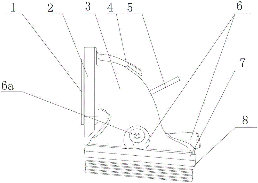
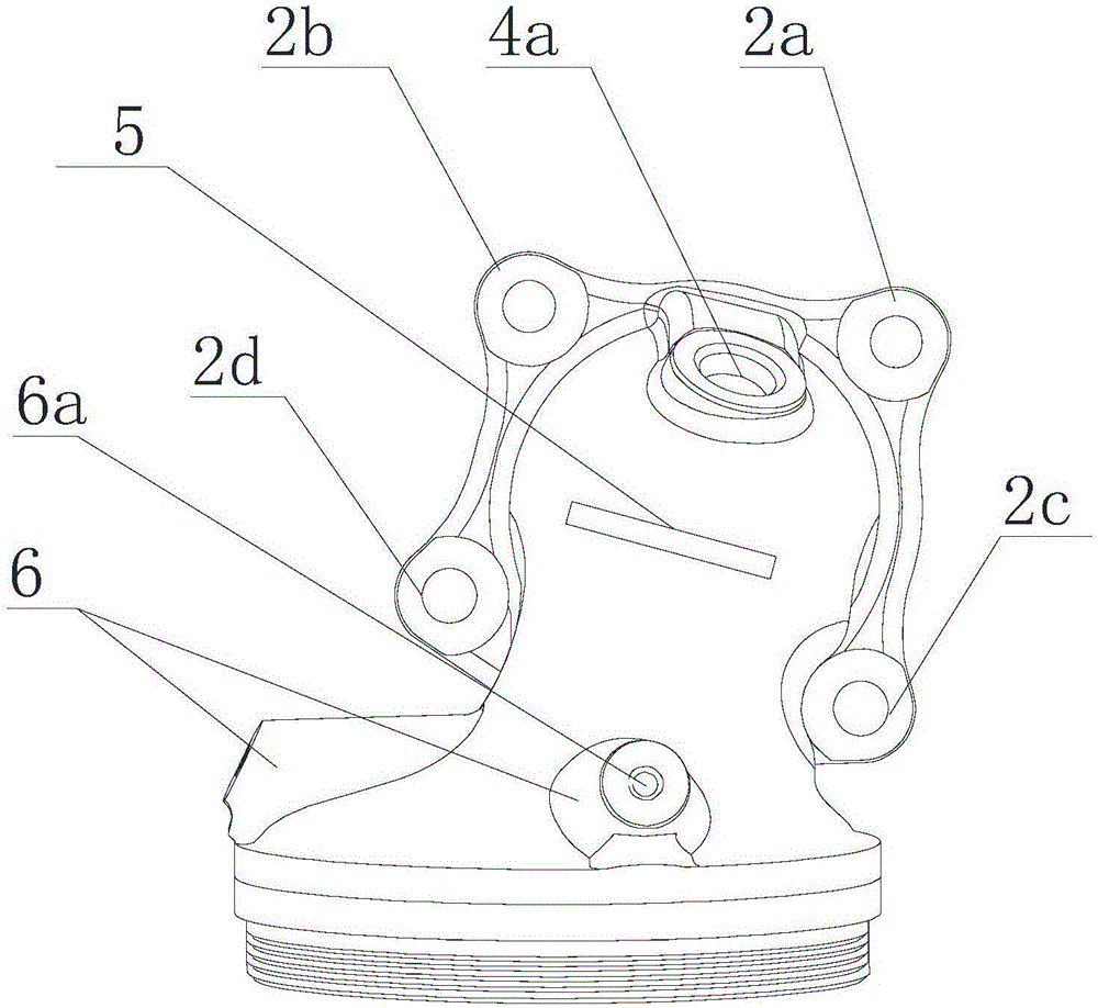
[0077] The automobile engine exhaust joint of the present embodiment, as Figure 1-5 As shown, it includes an elbow 3 and a carbon-removing sound-absorbing device 8. The elbow 3 is provided with an air inlet 1 and an air outlet 7. A heat sink 5 is arranged on the outer wall of the elbow 3. The carbon-removing sound-absorbing device 8 is connected with the outlet. The air port 7 is connected, and a sealing gasket 9 is provided between the carbon removal and sound absorption device 8 and the air outlet 7; the air inlet 1 is provided with a connecting flange 2, and the connecting flange 2 is surrounded by a first connecting part 2a and a second connecting part 2b, the third connecting portion 2c and the fourth connecting portion 2d. The elbow 3 is formed with two first circular positioning bosses 6 near the air outlet 7, and the middle of the top of the first circular positioning boss 6 is formed with a first positioning groove 6a. The elbow 3 is formed with a second circular po...
Embodiment 2
[0122] The automobile engine exhaust joint of the present embodiment, as Figure 1-5 As shown, it includes an elbow 3 and a carbon-removing sound-absorbing device 8. The elbow 3 is provided with an air inlet 1 and an air outlet 7. A heat sink 5 is arranged on the outer wall of the elbow 3. The carbon-removing sound-absorbing device 8 is connected with the outlet. The air port 7 is connected, and a sealing gasket 9 is provided between the carbon removal and sound absorption device 8 and the air outlet 7; the air inlet 1 is provided with a connecting flange 2, and the connecting flange 2 is surrounded by a first connecting part 2a and a second connecting part 2b, the third connecting portion 2c and the fourth connecting portion 2d. The elbow 3 is formed with two first circular positioning bosses 6 near the air outlet 7, and the middle of the top of the first circular positioning boss 6 is formed with a first positioning groove 6a. The elbow 3 is formed with a second circular po...
PUM
 Abstract
Description
Claims
Application Information
 - R&D Engineer
- R&D Manager
- IP Professional
- Industry Leading Data Capabilities
- Powerful AI technology
- Patent DNA Extraction
Browse by: Latest US Patents, China's latest patents, Technical Efficacy Thesaurus, Application Domain, Technology Topic, Popular Technical Reports.
© 2024 PatSnap. All rights reserved.Legal|Privacy policy|Modern Slavery Act Transparency Statement|Sitemap|About US| Contact US: help@patsnap.com


