
Semi-mechanical hole-forming method for super-large diameter hard rock cast-in-place pile

A super-large diameter, cast-in-place pile technology, applied in sheet pile wall, construction, infrastructure engineering and other directions, can solve the problems of low construction efficiency, high construction cost, long construction period, etc., to ensure the verticality of the hole and improve the construction efficiency. , The effect of reducing the difficulty of construction

Active Publication Date: 2017-05-31
ANHUI INST OF BUILDING RES & DESIGN
View PDF7 Cites 9 Cited by
  • Summary
  • Abstract
  • Description
  • Claims
  • Application Information

AI Technical Summary

Problems solved by technology

However, due to the deep burial depth and large diameter of the foundation of over-limit high-rise buildings (generally more than 2 meters), when the pile body is in the rock formation, even if the pile length is relatively short, there is great technical difficulty in manually excavating the pile hole. It is reflected in: the drill bit wears a lot, the construction cost is high, and the construction period is long, and the construction efficiency is low

Method used


Image

  • Semi-mechanical hole-forming method for super-large diameter hard rock cast-in-place pile
  • Semi-mechanical hole-forming method for super-large diameter hard rock cast-in-place pile
  • Semi-mechanical hole-forming method for super-large diameter hard rock cast-in-place pile

Examples


Embodiment Construction

[0023] The following will clearly and completely describe the technical solutions in the embodiments of the present invention with reference to the accompanying drawings in the embodiments of the present invention. Obviously, the described embodiments are only some, not all, embodiments of the present invention. Based on the embodiments of the present invention, all other embodiments obtained by persons of ordinary skill in the art without making creative efforts belong to the protection scope of the present invention.

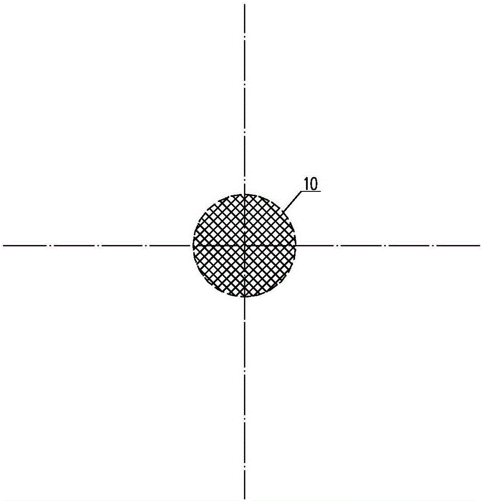
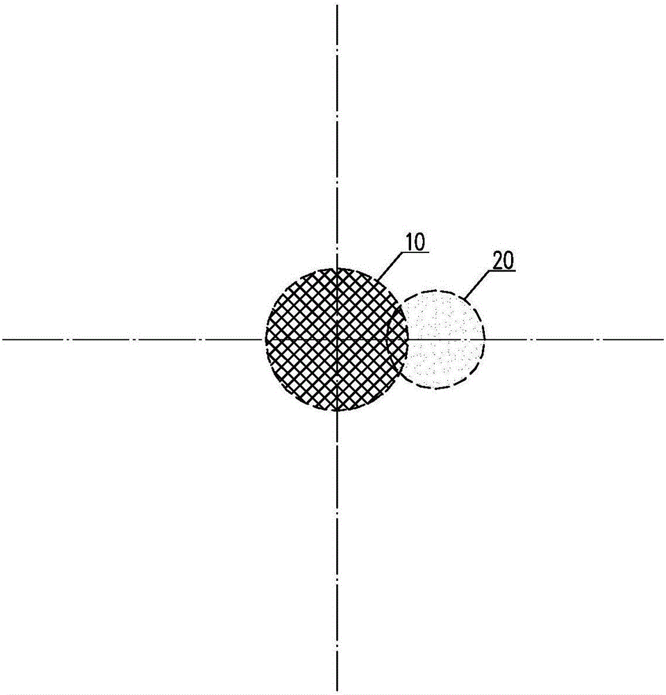
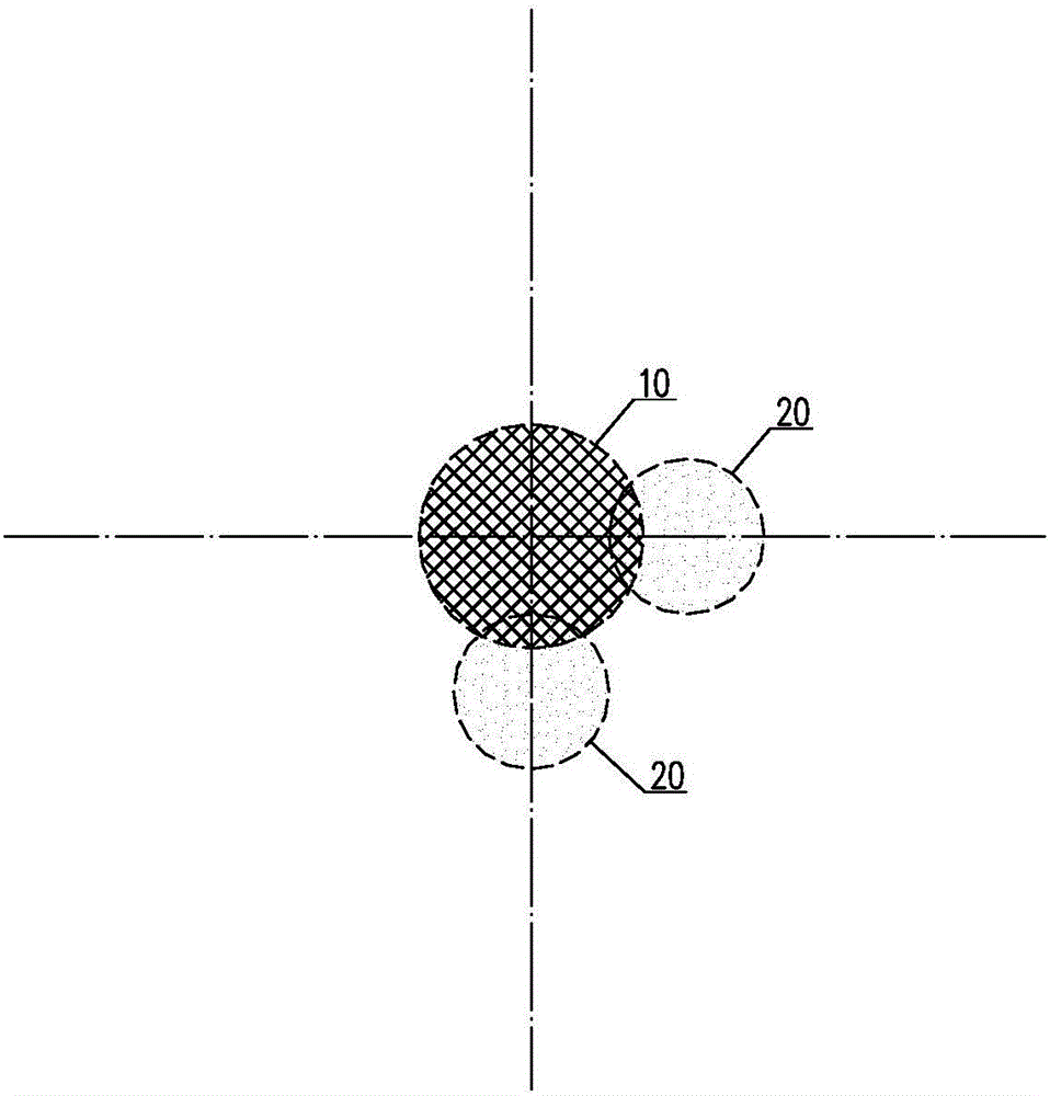
[0024] Such as Figures 1a-1f As shown, a semi-mechanical hole-forming method for super large-diameter hard rock cast-in-place piles, the diameter of the pile body of the cast-in-place piles is more than or equal to 2 meters, including the following steps:

[0025] S1, positioning and measuring the pile position, first adopt mechanical drilling to drill out the central pile hole 10, the hole center of the central pile hole 10 coincides with the pile position ce...


PUM


Abstract

The invention relates to a semi-mechanical hole-forming method for a super-large diameter hard rock cast-in-place pile. The semi-mechanical hole-forming method comprises the following steps that firstly a pile position is positioned and measured, specifically, at first, a central pile hole is drilled through mechanical hole drilling, the hole center of the central pile hole coincides with the center of the pile position, and the hole diameter of the central pile hole is 45-50% of the diameter of a pile body of the cast-in-place pile; then a plurality of peripheral side pile holes evenly distributed along the periphery of the central pile hole are drilled in the periphery of the central pile hole through mechanical hole drilling, and the hole diameter of each peripheral side pile hole is 30-35% of the diameter of the pile body of the cast-in-place pile; and finally, hole broadening operation is conducted at the bottom of the pile holes, the pile bottom diameter after the pile is broadened is 1.5-2 times the diameter of the pile body of the cast-in-place pile. According to the semi-mechanical hole-forming method for the super-large diameter hard rock cast-in-place pile, the construction schedule of a pile foundation can be ensured, and the difficulty that the cost of mechanical pile bottom broadening is high is solved; compared with a procedure, downward excavation from the ground, of a traditional man-dug pile, the man-dug pile is constructed after large excavation, large and deep excavation is not needed, so that construction safety is ensured, and cost is saved; and in addition, the hole-forming quality can be ensured through manual hole broadening and building.

Description

technical field [0001] The invention belongs to the technical field of hole forming of cast-in-place piles, in particular to a semi-mechanical hole-forming method for super-large-diameter hard rock cast-in-situ piles. Background technique [0002] Over-limit high-rise buildings often require a large single-column axial force, while large-diameter artificial excavated piles just have the advantage of large single pile bearing capacity, especially when the rock formation is relatively shallow, it will be very economical as the foundation of over-limit high-rise buildings. However, due to the deep burial depth and large diameter of the foundation of over-limit high-rise buildings (generally more than 2 meters), when the pile body is in the rock formation, even if the pile length is relatively short, there is great technical difficulty in manually excavating the pile hole. It is reflected in: the drill bit wears a lot, the construction cost is high, and the construction period i...

Claims


Application Information

Patent Timeline
Patent Type & Authority Applications(China)
IPC IPC(8): E02D5/34
CPCE02D5/34E02D2250/00
Inventor 赵时运王厚良曾伟钱礼平戴良军陈卫东陈刚秦旭飞马良浮
Owner ANHUI INST OF BUILDING RES & DESIGN
Learn More