
Non-contact refueling system

A refueling system and non-contact technology, which is applied in special dispensing devices, packaging, dispensing devices, etc., can solve the problem that refueling cannot be paid quickly and electronically

Inactive Publication Date: 2017-05-31
天津市技友先达科技股份有限公司
View PDF7 Cites 3 Cited by
  • Summary
  • Abstract
  • Description
  • Claims
  • Application Information

AI Technical Summary

Problems solved by technology

[0005] The purpose of the present invention is to provide a non-contact refueling system to solve the technical problem in the prior art that refueling cannot be fast and electronic payment

Method used


Image

  • Non-contact refueling system

Examples


Embodiment Construction

[0023] It should be noted that, in the case of no conflict, the embodiments of the present invention and the features in the embodiments can be combined with each other.

[0024] The present invention will be described in detail below with reference to the accompanying drawings and examples.

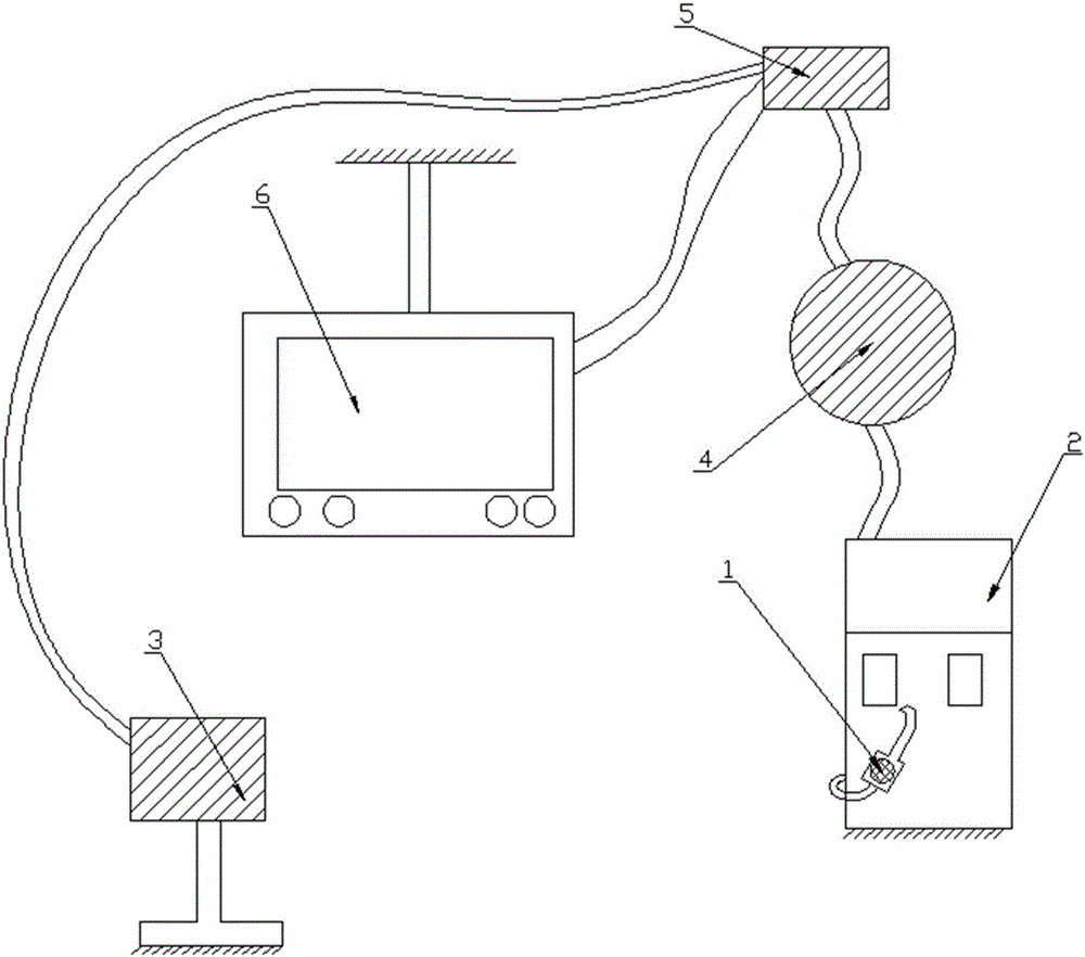
[0025] figure 1 It is a schematic structural diagram of a non-contact refueling system provided by the embodiment of the invention;

[0026] Such as figure 1 As shown, the RFID tag includes a first RFID tag 1 and a second RFID tag;

[0027] The fuel gun 2 is affixed with a first RFID tag 1 that can be identified by a first RFID reader-writer 4. The first RFID reader-writer 4 is located in a gas station, and a second RFID reader-writer for reading vehicle information is also provided in the gas station. Device 3, the second RFID label is affixed on the car;

[0028] In the case of automobile refueling, the first RFID reader-writer 4 is used to calculate the distance between the refuel...


PUM


Abstract

The invention provides a non-contact refueling system. The non-contact refueling system is characterized by comprising RFID tags, a refueling gun, RFID reader-writers and a processor; the first RFID tag which can be identified by the first RFID reader-writer is pasted on the refueling gun; the first RFID reader-writer is located in a refueling station; the refueling station is further internally provided with the second RFID reader-writer used for reading the automobile information; the second RFID tag is pasted on an automobile; and the first RFID reader-writer is electrically connected with the processor. According to the non-contact refueling system, the automobile information is identified and processed within the first time; during the refueling process of the automobile, the RFID reader-writers scan the RFID tags on the refueling gun and the automobile; after refueling is completed, the processor gives a result through processing; and after working personnel checks the result with a user, the processor deducts the automobile fuel cost prestored in the user RFID tags, the user does not need to get off the automobile, and the functions of rapid refueling and intelligent payment are achieved.

Description

technical field [0001] The invention belongs to the field of vehicle refueling, in particular to a non-contact refueling system. Background technique [0002] Gas station, usually refers to the replenishment station of retail gasoline and engine oil for automobiles and other motor vehicles, generally for adding fuel oil, lubricating oil, etc., the liquid is flowing, stirring, settling, filtering, shaking, spraying, splashing, Static electricity may be generated during flushing, pouring, etc. Static electricity often causes fires and explosions of flammable and explosive liquids. Two layers of electric charges with equal electric quantity and opposite signs are called electric double layers. The main reason for the formation of a double electric layer is that the liquid medium can be dissociated into positive and negative ions in different ways. There are many facilities in the gas station area, but static electricity mainly gathers in the oil storage tank area, oil pipelin...

Claims


Application Information

Patent Timeline
IPC IPC(8): B67D7/04B67D7/14
CPCB67D7/04B67D7/14
Inventor 胡刚
Owner 天津市技友先达科技股份有限公司
Learn More