
Movable rapid refueling system

A refueling system and mobile technology, applied in tank trucks, motor vehicles, liquid distribution, etc., can solve the problems of inconvenient construction of conventional gas stations, failure of gas stations, inconvenient refueling, etc., to achieve fast and convenient refueling , the effect of improving work efficiency

Active Publication Date: 2020-11-17
临夏海螺水泥有限责任公司 +3
View PDF5 Cites 2 Cited by
  • Summary
  • Abstract
  • Description
  • Claims
  • Application Information

AI Technical Summary

Problems solved by technology

[0002] At present, in remote mountainous areas, mining areas and disaster-stricken areas, due to the remote location, it is inconvenient to build conventional gas stations, and the cost will be very high. On the other hand, once the project is over, the gas station will be useless

Method used


Image

  • Movable rapid refueling system
  • Movable rapid refueling system
  • Movable rapid refueling system

Examples


Embodiment 1

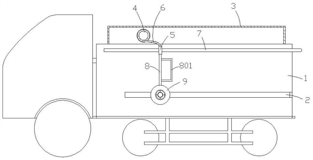
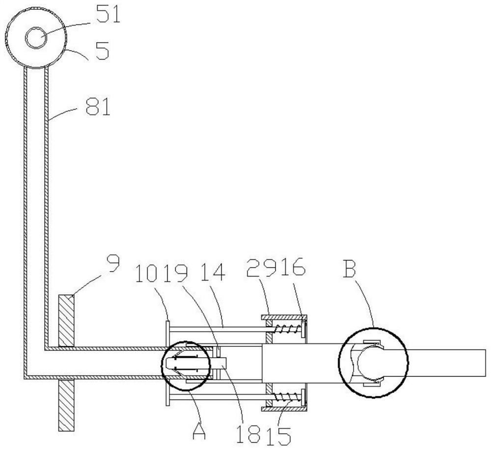
[0033] see Figure 1-2 ,, Figure 4-7 , a mobile fast refueling system, including a refueling truck equipped with an oil tank 1, an oil outlet assembly is slidably connected to the outside of the oil tank 1, a top cover 3 is installed on the top of the oil tank 1, and a winding column 4 is installed inside the top cover 3 A soft oil delivery pipe 6 is wound around the column 4, one end of the oil delivery pipe 6 communicates with the inside of the oil tank 1 through an oil pump, and the other end of the oil delivery pipe 6 is connected with the oil outlet assembly.

[0034] The oil outlet assembly includes a beam 7 fixed on the top of the outer wall of the oil tank 1 .

[0035] A collar 5, said collar 5 is slidably socketed outside the beam 7, and can slide along the extension direction of the beam 7, the collar 5 is a hollow structure, the inside of the collar 5 communicates with the oil delivery pipe 6, and the collar 5 is provided with an outlet oil hole.

[0036] A hard...

Embodiment 2

[0048] see image 3 , different from Embodiment 1, the clamping mechanism described in this embodiment includes a positioning sleeve 29, the inner wall of the positioning sleeve 29 has internal threads, the outer wall of the second convex plate 17 has external threads, and the positioning sleeve 29 is spirally sleeved on the second convex plate 17. On the outside of the second convex plate 17 , a flange is provided on the side of the positioning sleeve 29 close to the limiting block 16 , and the flange is used to compress the limiting block 16 .

[0049] This embodiment can be further improved. The annular plate of the fixed plug 18 is set as a plate-shaped structure that cannot pass through the oil. hole, the end of the plug 18 away from the tapered cylinder 30 passes through the annular plate 19, and opens an oil outlet hole communicating with the inside, so that the oil can be further filtered, and a filter element can be set in the plug 18 to Filter the oil passing throug...


PUM


Abstract

The invention discloses a movable rapid refueling system. The movable rapid refueling system comprises a refueling vehicle provided with an oil tank, wherein an oil outlet assembly is slidably connected to the outer side of the oil tank; a top cover installed at the top of the oil tank; a winding column installed in the top cover; a soft oil conveying pipe is wound around the winding column; one end of the oil conveying pipe communicates with the interior of the oil tank through an oil pump; the other end of the oil conveying pipe is connected with the oil outlet assembly; the oil outlet assembly comprises a cross beam and a lantern ring; the cross beam is fixed to the top of the outer wall of the oil tank; the lantern ring is slidably connected outside the cross beam in a sleeving mannerand capable of sliding in the extending direction of the cross beam; the lantern ring is of a hollow structure; the interior of the lantern ring communicates with the oil conveying pipe; an oil outlethole is formed in the lantern ring, and a hard oil conveying pipe is arranged on the lantern ring; the top end of the hard oil conveying pipe is connected with the oil outlet hole; and a conical barrel is fixed into the bottom end of the hard oil conveying pipe. The movable rapid refueling system facilitates movable refueling, and is capable of rapidly adjusting the position according to oiling points; and moreover, oil conveying pipelines are arranged in order, so that repeated use is facilitated, pipeline knots cannot be caused, and the operation is simple and convenient.

Description

technical field [0001] The invention relates to the field of refueling equipment, in particular to a mobile fast refueling system. Background technique [0002] At present, in remote mountainous areas, mining areas and disaster-stricken areas, due to the remote location, it is inconvenient to build conventional gas stations, and the cost will be very high. It is inconvenient to refuel at the traditional gas station, on the other hand, once the project is over, the gas station will be useless. Therefore, it is very important and urgent to develop a new type of portable and mobile refueling equipment to meet the refueling needs of these special areas. Contents of the invention [0003] The purpose of the present invention is to provide a mobile fast refueling system to solve the problems raised in the above background technology. [0004] To achieve the above object, the present invention provides the following technical solutions: [0005] A mobile fast refueling system,...

Claims


Application Information

Patent Timeline
Patent Type & Authority Applications(China)
IPC IPC(8): B67D7/04B67D7/84B60P3/22
CPCB67D7/04B67D7/845B60P3/22B60P3/224B67D2210/00136
Inventor 陆克松王军锋张少栋冯宇河
Owner 临夏海螺水泥有限责任公司
Learn More