
On-wing cleaning injection system for aeroengines

An aero-engine and injection system technology, applied in aircraft cleaning and other directions, can solve the problems of inability to adjust the spatial position of the nozzle, cumbersome installation process, increase the cost of cleaning aircraft engines, etc., and achieve the effect of reducing time, budget and waste.

Active Publication Date: 2017-05-31
CIVIL AVIATION UNIV OF CHINA
View PDF5 Cites 5 Cited by
  • Summary
  • Abstract
  • Description
  • Claims
  • Application Information

AI Technical Summary

Problems solved by technology

However, because there are too many types of aircraft belonging to the airline company, a variety of different types of nozzle brackets are required to adapt to different types of aircraft and engines. Generally, the nozzle bracket cannot adjust the spatial position of the nozzle, and one bracket can only clean one. different types of engines, which increases the cost of cleaning aircraft engines for airlines, and the installation process is cumbersome

Method used


Image

  • On-wing cleaning injection system for aeroengines
  • On-wing cleaning injection system for aeroengines
  • On-wing cleaning injection system for aeroengines

Examples


Embodiment Construction

[0018] It should be noted that, in the case of no conflict, the embodiments of the present invention and the features in the embodiments can be combined with each other.

[0019] In describing the present invention, it should be understood that the terms "center", "longitudinal", "transverse", "upper", "lower", "front", "rear", "left", "right", " The orientations or positional relationships indicated by "vertical", "horizontal", "top", "bottom", "inner" and "outer" are based on the orientations or positional relationships shown in the drawings, and are only for the convenience of describing the present invention and Simplified descriptions, rather than indicating or implying that the device or element referred to must have a particular orientation, be constructed and operate in a particular orientation, and thus should not be construed as limiting the invention. In addition, the terms "first", "second", etc. are used for descriptive purposes only, and should not be understood ...


PUM


Abstract

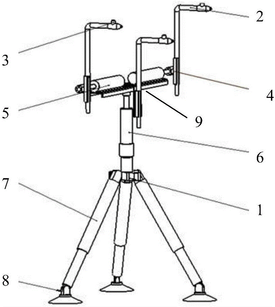
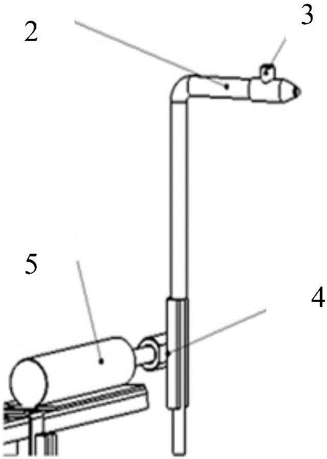
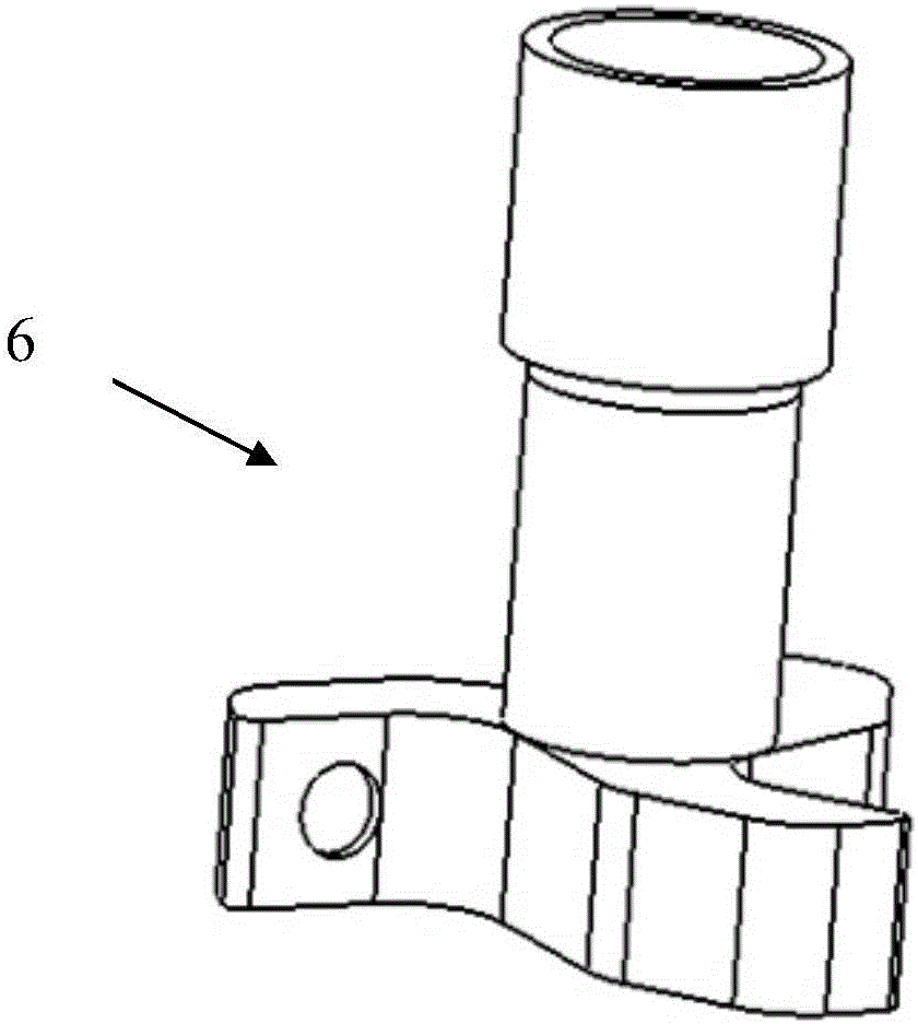
An on-wing cleaning injection system for aeroengines comprises a base, nozzles, nozzle regulating devices, locating clips, a horizontal regulating device, a height regulating device, support legs, suckers and a support plate. The on-wing cleaning injection system for aeroengines of the invention has following beneficial effects: first: the number of multiple different supports is reduced effectively to reduce waste and therefore the budget for aviation companies and airports in cleaning aircraft engines; second: the structure is adjustable and the suckers are fixed on the ground so as to reduce time for cleaning for aviation companies and airports; third: the position of the nozzles can be adjusted and the height is adjustable so that the system is suitable for the cleaning of aircraft engines of different types.

Description

technical field [0001] The invention belongs to the technical field of aviation ground special equipment, in particular to an aeroengine on-wing cleaning injection system. Background technique [0002] When an aircraft engine works for a long time, the output power of the turbine and the flow quality of the compressor will gradually decrease. This is because the pollutants in the air will enter the engine with the airflow and deposit on the surface of the engine blades, which will change the axial shape of the blades, thereby affecting the intake air flow, compression ratio and working efficiency. Therefore in this case the engine must increase the turbine inlet temperature and accelerate fuel consumption to compensate for the power loss caused by the above pollutants. [0003] Research on aircraft engine cleaning technology has always been a field with potential for development. When the engine blades need to be cleaned, the previous practice is to disassemble the engine b...

Claims


Application Information

Patent Timeline
IPC IPC(8): B64F5/30
Inventor 石旭东闫至骐龙飞企唐杰王立文
Owner CIVIL AVIATION UNIV OF CHINA
Learn More