
Digital controlled lathe thermal error measuring compensation system and method

A technology of CNC lathe and compensation system, applied in the field of CNC machine tools

Active Publication Date: 2017-05-31
XI AN JIAOTONG UNIV
View PDF7 Cites 50 Cited by
  • Summary
  • Abstract
  • Description
  • Claims
  • Application Information

AI Technical Summary

Problems solved by technology

[0003] The purpose of the present invention is to aim at the coupling problem of the thermal error of the spindle and the feed axis of the CNC lathe, and propose a thermal error measurement and compensation system and compensation method for the CNC lathe, and carry out real-time comprehensive modeling of the thermal error of the spindle and the feed axis system to solve the problem. The axial thermal expansion and contraction of the CNC lathe and the radial thermal tilt thermal error related to the temperature and the current position of the tool can improve the machining accuracy of the CNC machine tool

Method used


Image

  • Digital controlled lathe thermal error measuring compensation system and method
  • Digital controlled lathe thermal error measuring compensation system and method
  • Digital controlled lathe thermal error measuring compensation system and method

Examples


Embodiment Construction

[0064] The present invention will be further described in detail below in conjunction with the accompanying drawings and specific implementation.

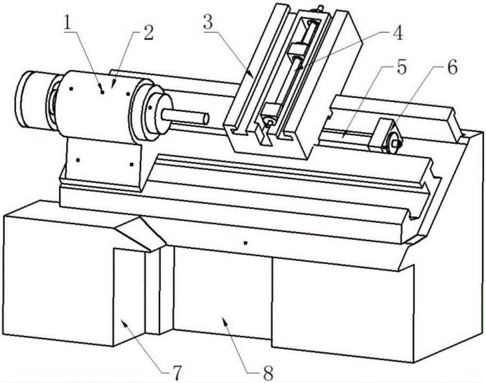
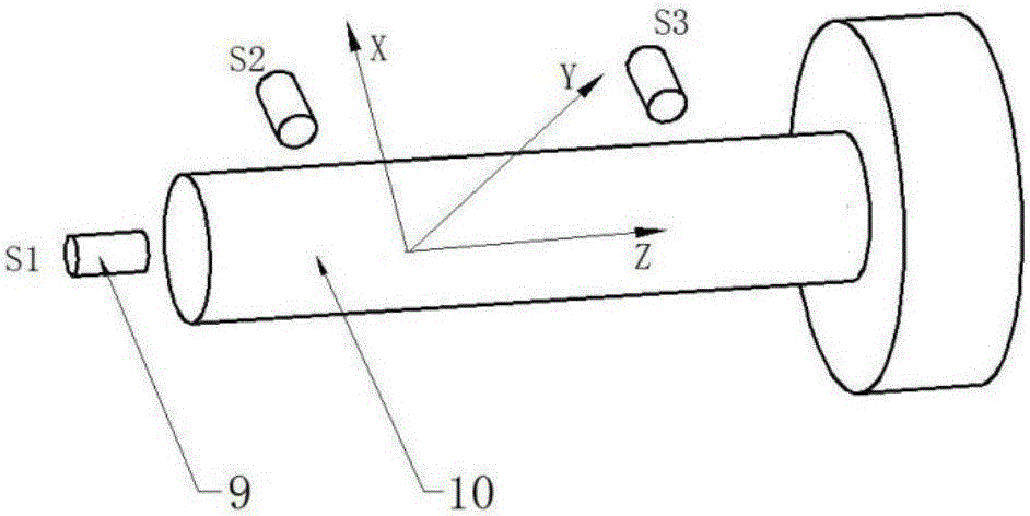
[0065] Such as figure 1 , figure 2 As shown, a thermal error measurement and compensation system for a CNC lathe includes an eddy current displacement sensor 9, a platinum resistance temperature sensor 1, a laser interferometer, a displacement acquisition and processing module, a thermal error compensation module and a PC, wherein the eddy current displacement sensor 9 and The displacement acquisition and processing module is connected and transmits the real-time measured spindle rod 10 and tool position information. The displacement acquisition and processing module is connected to the PC through the serial port, and the laser interferometer is connected to the PC to measure the positioning error of the measuring point of the feed system. Platinum The resistance temperature sensor 1 is connected with the thermal error compensati...


PUM


Abstract

The invention discloses a digital controlled lathe thermal error measuring compensation system and method. The system comprises an eddy current displacement sensor, a platinum resistor temperature sensor, a laser interferometer, a displacement collecting and processing module, a thermal error compensation module and a PC. The platinum resistor temperature sensor measures the temperature of a lathe body heat sensitive point, the eddy current displacement sensor measures heat deformation of a spindle, the laser interferometer measures the locating error of a feeding system, and the spindle and a feeding shaft system are subjected to real-time thermal error comprehensive modeling. The thermal error compensation module compensates for axial heat expansion and radial heat inclination of a spindle workpiece in real time according to the temperature of the heat sensitive point and the coordinate value of a tool. The coupling problem of the digital controlled lathe spindle and the feeding shaft thermal error is solved, the thermal error can be compensated for in real time, and the machining precision of a digital controlled lathe is improved.

Description

technical field [0001] The invention relates to the technical field of numerical control machine tools, in particular to a thermal error measurement and compensation system and compensation method of a numerical control lathe. Background technique [0002] Problems such as poor accuracy retention, one of the key factors affecting the accuracy of machine tools, thermal error accounts for 40% to 70% of the overall error of the machine tool, and the proportion is even larger for high-precision CNC lathes. Thermal error compensation is the most economical and effective means to solve the thermal problems of machine tools, and it is of great significance for improving the precision of CNC machines and improving the performance of machine tools. During the working process of the CNC lathe, due to the heat generated by the friction of the spindle system bearing, the thermal drift of the spindle will occur. The frictional heat generated by the screw nut pair of the feed system and t...

Claims


Application Information

Patent Timeline
IPC IPC(8): B23Q15/18B23Q17/09
CPCB23Q15/18B23Q17/0985
Inventor 陶涛陈同侯瑞生杜宏洋颜宗卓
Owner XI AN JIAOTONG UNIV
Learn More