Civil air defense door tool and civil air defense door manufacture process using civil air defense door tool
A technology of manufacturing process and air defense door, applied in the direction of manufacturing tools, other manufacturing equipment/tools, auxiliary devices, etc., can solve the problems of high labor intensity, large workload, low processing efficiency of concrete door leaves, etc., to improve work efficiency, welding Convenience, the effect of reducing operation steps and workload
- Summary
- Abstract
- Description
- Claims
- Application Information
AI Technical Summary
Problems solved by technology
Method used
Image

Examples
Embodiment 1
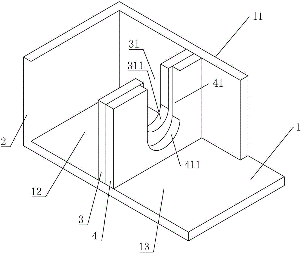
[0032] Embodiment 1: civil air defense door tooling, such as Figure 1 to Figure 2As shown, it includes a square bottom plate 1, the bottom plate 1 is sequentially welded with a first limiting plate 2, a second limiting plate 3 and a third limiting plate 4 along the length direction, and one side of the bottom plate 1 is also welded to a piece perpendicular to the first A baffle plate 11 of a limiting plate 2, one side of the first limiting plate 2 is welded on the baffle plate 11, and a first limiting cavity 12 is formed between the first limiting plate 2, the baffle plate 11 and the bottom plate 1, and is used for Put in the first fixing plate 61 .
[0033] The second limiting plate 3 is located between the first limiting plate 2 and the third limiting plate 4 , the second limiting plate 3 is parallel to the first limiting plate 2 and one side is welded on the baffle plate 11 . The second limiting plate 3 is provided with a first limiting direction, the upper end of the fir...
Embodiment 2
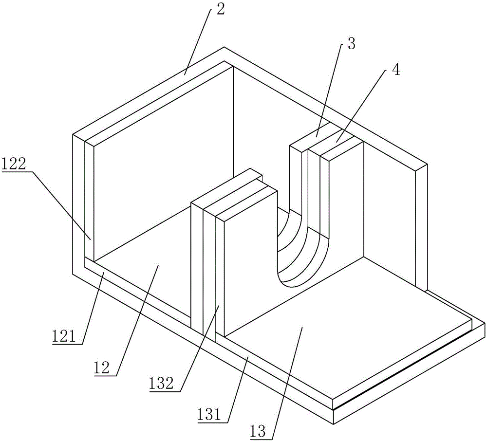
[0036] Embodiment 2: civil air defense door tooling, including embodiment 1, such as figure 1 and image 3 As shown, a plurality of first adjusting plates 121 parallel to the bottom plate 1 and a plurality of second adjusting plates 122 parallel to the first limiting plate 2 are placed in the first limiting cavity 12, and the first fixing plate 61 is placed in the second position. When inside a limiting cavity 12, the lower end of the first fixing plate 61 is in contact with the first adjusting plate 121, the end surface of the first fixing plate 61 does not touch the end surface of the first limiting plate 2, and the end surface of the first fixing plate 61 is in contact with the second adjusting plate 121. on the end face of the adjustment plate 122 . By changing the number of the first adjusting plate 121, the distance between the first fixing plate 61 and the bottom plate 1 can be adjusted, and by changing the number of the second adjusting plate 122, the distance between...
Embodiment 3
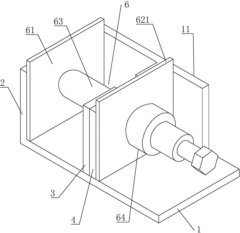
[0039] Embodiment 3: civil air defense door tooling, including embodiment 1, such as figure 1 , Figure 4 to Figure 5 As shown, a first limiting block 32 is inserted into the first limiting slot 31, and one end of the first limiting block 32 is provided with an arc-shaped first limiting concave surface 321. When the first limiting slot 31 is placed with When the shaft 63 is fixed, the first limiting concave surface 321 is pressed against the outer peripheral wall of the fixed shaft 63 . A second limiting block 42 is inserted into the second limiting groove 41, and one end of the second limiting block 42 is provided with an arc-shaped second limiting concave surface 421. When the second limiting groove 41 is placed with a shaft sleeve 64 , when the second limit block 42 is plugged into the second limit facing inward, the second limit concave surface 421 is in contact with the outer circumferential wall of the shaft sleeve 64 .
[0040] When the fixed shaft 63 is welded on the...
PUM
 Abstract
Description
Claims
Application Information
 - R&D
- Intellectual Property
- Life Sciences
- Materials
- Tech Scout
- Unparalleled Data Quality
- Higher Quality Content
- 60% Fewer Hallucinations
Browse by: Latest US Patents, China's latest patents, Technical Efficacy Thesaurus, Application Domain, Technology Topic, Popular Technical Reports.
© 2025 PatSnap. All rights reserved.Legal|Privacy policy|Modern Slavery Act Transparency Statement|Sitemap|About US| Contact US: help@patsnap.com