
Compound linear guide having a fastening means

A technology of fixing device and guiding element, applied in the field of conveying system, can solve the problems of expensive, difficult to manufacture, etc.

Active Publication Date: 2017-05-24
WESEE LTD
View PDF6 Cites 3 Cited by
  • Summary
  • Abstract
  • Description
  • Claims
  • Application Information

AI Technical Summary

Problems solved by technology

However, they have the disadvantage of being very difficult and expensive to manufacture

Method used


Image

  • Compound linear guide having a fastening means
  • Compound linear guide having a fastening means
  • Compound linear guide having a fastening means

Examples


Embodiment Construction

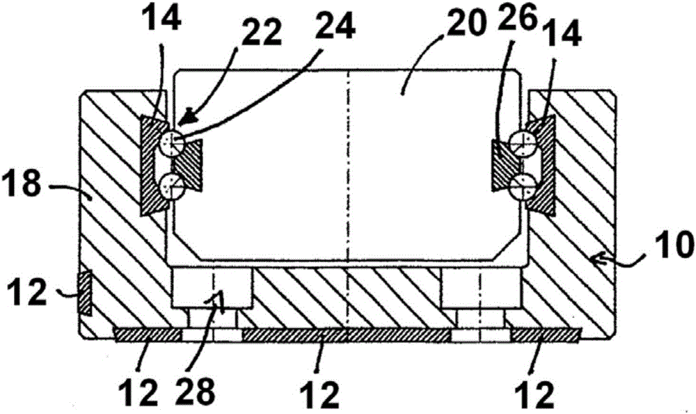
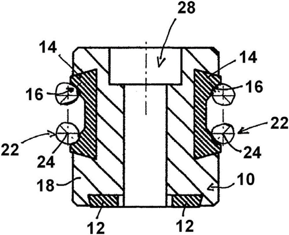
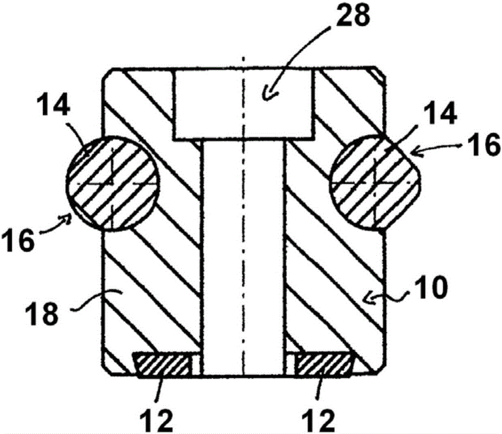
[0032] Figure 1 to Figure 4 Different embodiments of the guide rail 10 are shown, which are equipped with fixing means 12 for fixing the guide rail 10 to magnetic clamping means, not shown. Furthermore, each guide rail 10 is equipped with two guide elements 14 each having a guide surface 16 . Each fixing device 12 and each guide element 14 are attached to a non-magnetic light metal base 18 .

[0033] figure 1 An embodiment is shown in which the guide rail 10 has a U-shape and is partially engaged around the slider 20 from the outside. The slide 20 on which the object to be transported is arranged is linearly displaceably supported at the guide rail 10 by a bearing 22 . The bearing 22 comprises a plurality of roller elements 24 which are arranged between the rail-side guide element 14 and the slide-side guide part 26 and are in contact with the guide surface 16 . The guide element 14 , the guide part 26 and the fastening device 12 are inserted into trapezoidal grooves form...


PUM


Abstract

The invention relates to a transfer system for transporting objects, comprising: a guide rail, which has a light-metal main body and at least one guide element, which is connected to the light-metal main body and has a guide surface; a slide for accommodating at least one object; and a bearing, which interacts with the guide element and supports the slide on the guide rail in such a way that the slide can move linearly; wherein the guide rail has at least one magnetic fastening means, which makes it possible to temporarily fasten the guide rail by means of a magnetic clamping device, in particular in order to process the guide surface.

Description

technical field [0001] The invention relates to a conveyor system for transporting objects, the conveyor system having a guide rail with a light metal base body and at least one guide element connected to the light metal base body and having a guide surface; with a slide for receiving at least one object and having a bearing linearly displaceably supporting the slider at the rail. Background technique [0002] Conveyor systems of the aforementioned named type are used, for example, in automation technology to transport objects from one location to another; for example, from one production step to the next. For this purpose, the object is positioned on the slide and the slide travels along the rails. [0003] It is known to manufacture rails as composite elements. In such so-called composite linear guides, the main body is made, for example, of a light metal such as aluminum. A steel wire or a steel shaft is introduced into the body, for example by insertion or rolling, an...

Claims


Application Information

Patent Timeline
Patent Type & Authority Applications(China)
IPC IPC(8): F16C29/00F16C33/61F16C33/64F16C29/06
CPCF16C29/005F16C29/063F16C29/0642F16C29/065F16C33/61F16C33/64F16C2226/18F16C2326/58B23Q3/15Y10T29/49641F16C2202/40F16C2220/60
Inventor 海因茨·格林纳
Owner WESEE LTD
Learn More