
Oscillating slide machine

A slide valve and mechanical technology, applied in the field of swing slide valve machinery, can solve problems such as pulsation, limited bending angle, and stability of swing webs, and achieve the goals of reducing pulsation and cavitation, increasing maximum eccentricity, and improving operating performance Effect

Active Publication Date: 2008-07-30
MAHLE INT GMBH
View PDF5 Cites 0 Cited by
  • Summary
  • Abstract
  • Description
  • Claims
  • Application Information

AI Technical Summary

Problems solved by technology

[0007] However, experiments with such asymmetrical swing claws have shown that (according to Figures 1, 5 and 6 of the above-mentioned patent application description) the swing slide valve machinery with asymmetrical swing claws has the following serious disadvantages, such as: irregular torque Variations, severe pulsation (especially at maximum eccentricity), adjustment difficulties (especially at high speeds due to clamping effects), severe wear marks in the area of ​​the swing foot (Pendelfuβ), swing bellies The stability problem of the plates and the resulting severe limitation of the bending angle, as well as resulting in a low efficiency of about 5% to 10%, all of which necessarily require a very high and absolutely necessary manufacturing precision, so that due to the swing jaw The asymmetric structure of the conventional swing slide valve machine significantly increases the high manufacturing costs of the conventional swing slide valve, so compared with the structural form of the swing slide valve machine with symmetrical swing claws proposed in DE 195 32 703 C1, in this class The asymmetric swing jaws used in the machine have no advantages, on the contrary, they even have disadvantages
[0008] Therefore, from an economic point of view, it was not possible to guarantee an efficient and functionally reliable continuous operation with these asymmetrical swing jaws described in DE 101 02 531 A1 in swing slide valve machines of the time

Method used


Image

  • Oscillating slide machine
  • Oscillating slide machine
  • Oscillating slide machine

Examples


Embodiment Construction

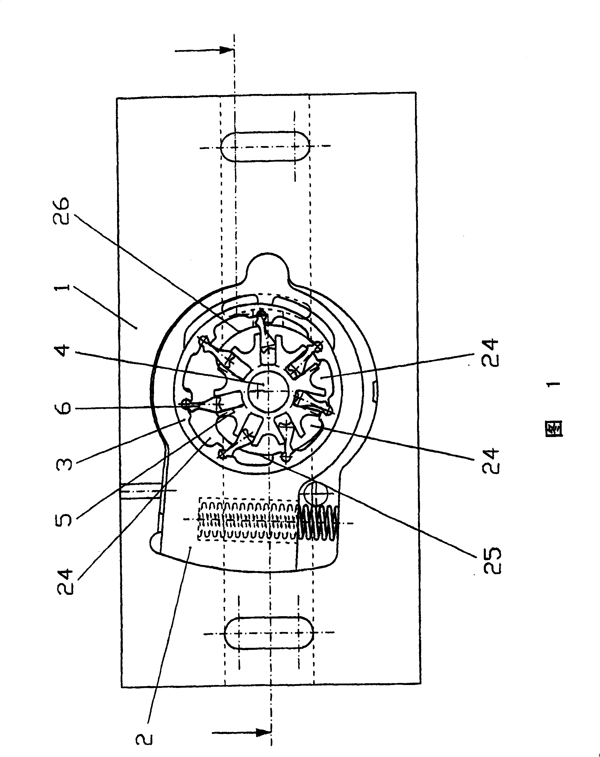
[0036] FIG. 1 shows a possible embodiment of the oscillating slide valve mechanism according to the invention in a sectional side view. A control slide valve 2 is arranged in the housing 1 . The outer runner 3 of a runner set is rotatably arranged in the control slide.

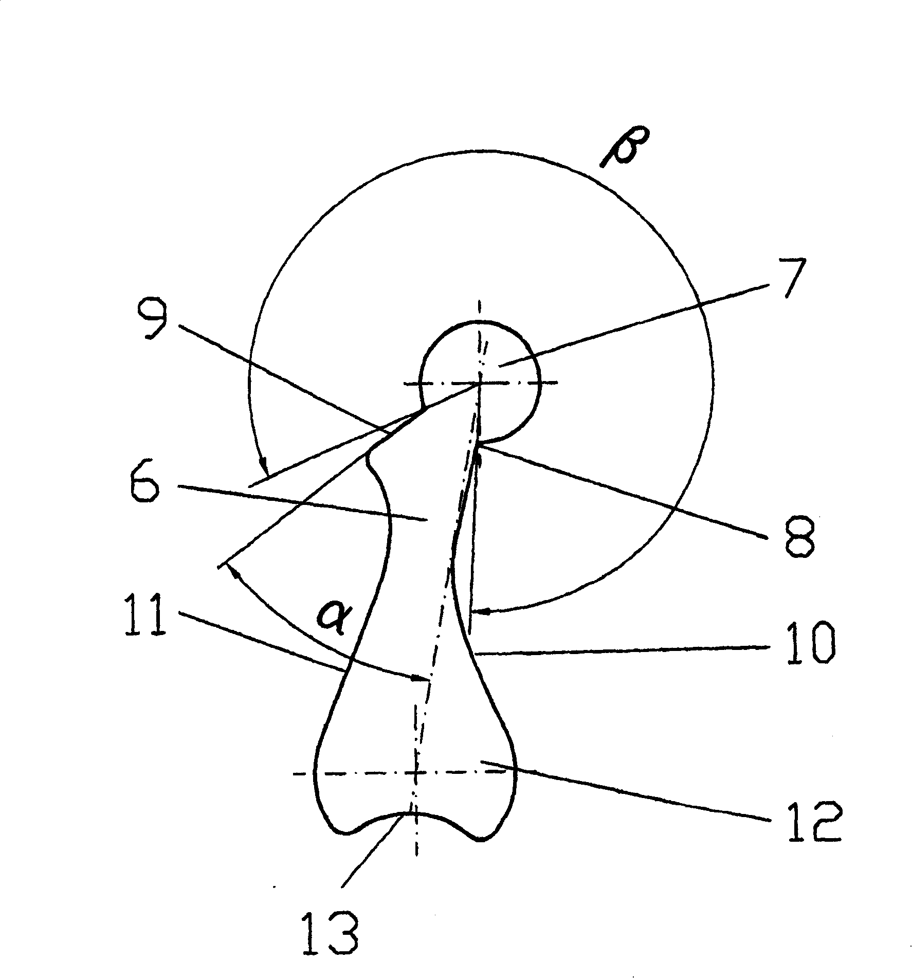
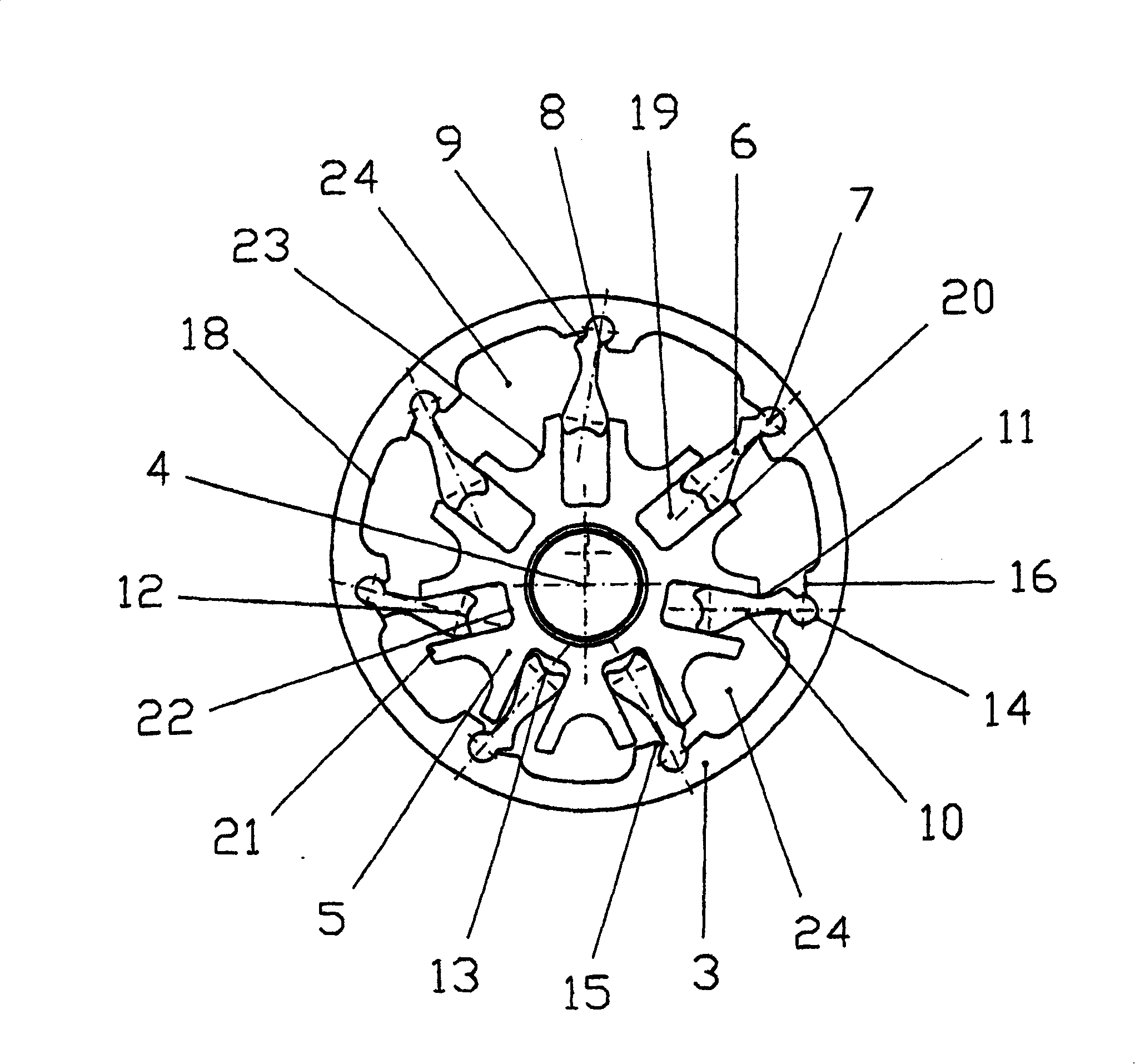
[0037] This runner set consists of an inner runner 5 arranged on a drive shaft 4 , which is connected to the outer runner 3 via seven oscillating webs 6 for rotational movement.

[0038] The individual pump chamber volumes of the pump chambers 24 formed between the adjacent swinging webs 6, the outer runner 3 and the inner runner 5 successively move to a maximum volume when the drive shaft 4 rotates one revolution and then Move to a minimal volume (or vice versa).

[0039] With the increased volume of the pump chamber 24 , the medium to be conveyed is sucked into the pump chamber 24 through suction openings 25 provided in the housing 1 and / or in the housing cover.

[0040] Offset by 180° in the direction of...


PUM


Abstract

The invention relates to an oscillating slide machine working on an eccentric circulatory motion, whereby the oscillation guide grooves ( 19 ) on the inner rotor ( 5 ) are provided with groove front edges ( 20 ) and groove rear edges ( 21 ) of differing heights, such that the diameter of the imaginary circle ( 17 ), connecting all groove front edges ( 20 ), is smaller than the diameter of the circle connecting all the groove rear edges ( 21 ).

Description

technical field [0001] The invention relates to an oscillating slide valve mechanism which works by means of an eccentric cyclic movement. Background technique [0002] Prior art FR 980 766 and DE 195 32 703 C1 respectively propose a swing slide valve mechanism with a rotatably mounted inner wheel and an equally rotatably mounted outer wheel driven by a oscillating cam. The flow rate can be changed by changing the eccentricity between the inner runner and the outer runner. In this form of construction, the symmetrically arranged oscillating cams are each rotatably arranged with their circular heads in the recess of the rotatably supported outer wheel, and are slidably arranged with their conical ends corresponding to the heads. in the groove of the inner runner. In this form of construction, the synchronous operation between the eccentrically running inner runner and the corresponding outer runner is ensured by the permissible play between the inner runner and the swing cl...

Claims


Application Information

Patent Timeline
Patent Type & Authority Patents(China)
IPC IPC(8): F04C2/348
CPCF04C2/332F04C2240/20F04C2/348Y10T74/18056
Inventor 冈瑟·比兹
Owner MAHLE INT GMBH
Learn More