
Waste heat recovery steam production quality improving equipment applicable to industrial enterprises

A waste heat recovery and enterprise technology, applied in lighting and heating equipment, energy industry, steam boilers, etc., can solve the problem of unstable output of waste heat recovery steam turbine generator sets, unstable steam production flow of waste heat recovery, and low effective utilization rate of equipment, etc. problems, to achieve the effect of compact structure, short start-up time, and reduced heat loss

Inactive Publication Date: 2017-05-24
北京福生智源科技有限公司
View PDF9 Cites 0 Cited by
  • Summary
  • Abstract
  • Description
  • Claims
  • Application Information

AI Technical Summary

Problems solved by technology

[0003] For industrial enterprises, production is the main business, and waste heat recovery is a sideline. In the case of cyclical peak and valley changes in production, affected by production conditions, the pressure and temperature of waste heat recovery steam production fluctuate, and waste heat recovery steam production flow It is also not constant, resulting in the output of waste heat recovery steam turbine generator set not being stable at the design value, resulting in poor efficiency of waste heat recovery and low effective utilization of equipment
The steam quality of the redundant steam delivery pipe network for downstream users is also unstable, with high hydrophobicity and serious heat loss

Method used


Image

  • Waste heat recovery steam production quality improving equipment applicable to industrial enterprises
  • Waste heat recovery steam production quality improving equipment applicable to industrial enterprises
  • Waste heat recovery steam production quality improving equipment applicable to industrial enterprises

Examples


Embodiment Construction

[0024] The present invention will be described in detail below in conjunction with the accompanying drawings and specific embodiments.

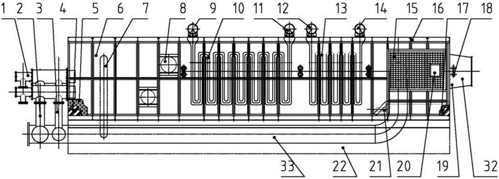
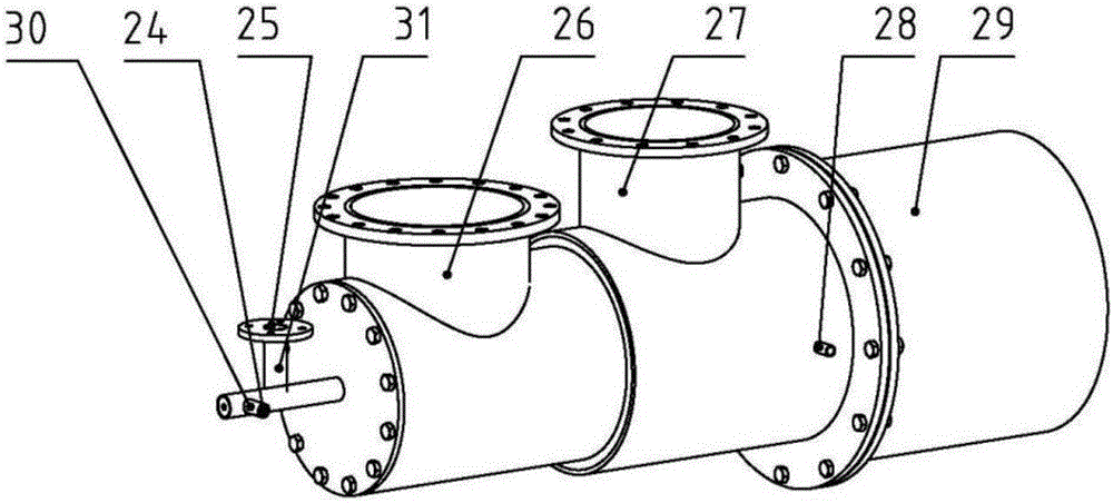
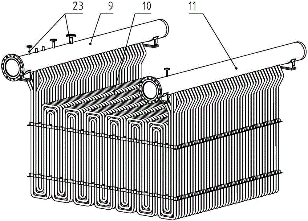
[0025] The present invention is applicable to waste heat recovery steam production quality improvement equipment of industrial enterprises, and its structure is as follows figure 1 As shown, a steel structure body 16 is included. The steel structure body 16 is mainly composed of I-shaped steel, channel steel, angle steel and steel plates through welding. One end of the steel structure body is connected with a combustion-supporting air pipeline 3. The combustion-supporting air pipeline 3 Together with the auxiliary fuel pipeline 2, it is connected to the burner 1, and the other end of the steel structure body opposite to this end is connected with a chimney connecting pipe 32; The refractory brick 5 is covered with an outer guard plate 4, and the refractory brick 5 is used for heat insulation protection of the equipment. The chamber surrounded...


PUM


Abstract

The invention discloses a waste heat recovery steam production quality improving equipment applicable to industrial enterprises. The waste heat recovery steam production quality improving equipment comprises a steel structure body, wherein a combustion air pipeline is connected with one end part of the steel structure body, the combustion air pipeline and an auxiliary fuel pipeline are connected with a combustor, and a chimney communicating pipe is connected with the other end part, opposite to the end part, of the steel structure body; refractory bricks are piled up in the steel structure body near the combustion air pipeline, and a chamber surrounded by the refractory bricks constitutes a combustion chamber; the combustion chamber is connected with a cold-blast air mixing pipe, and a high pressure superheater, a low-pressure superheater and an air preheater are arranged at the back of the combustion chamber; the air preheater is communicated with the combustion air pipeline and the auxiliary fuel pipeline through air communicating pipes, and an inlet of the air preheater is connected with a combustion fan through a combustion fan port; and an instrument port and an induced draft fan port are arranged on the outer wall of the chimney communicating pipe, and the induced draft fan port is connected with an induced draft fan. The waste heat recovery steam production quality improving equipment provided by the invention has the advantages of ensuring steam flow and pressure, and improving steam production temperature.

Description

technical field [0001] The invention belongs to the technical field of waste heat recovery equipment, and in particular relates to waste heat recovery steam production quality improvement equipment suitable for industrial enterprises. Background technique [0002] A large amount of waste heat resources are usually generated during the process of industrial enterprises. With the continuous development of technology, most of the high-quality physical energy and chemical energy have been effectively recovered through system upgrading and transformation. The main form of recovery is steam generation , The recovered steam has two main purposes: (1) for the steam turbine to generate electricity; (2) for the downstream users of the plant area through the steam pipeline network. [0003] For industrial enterprises, production is the main business, and waste heat recovery is a sideline. In the case of cyclical peak and valley changes in production, affected by production conditions, ...

Claims


Application Information

Patent Timeline
Patent Type & Authority Applications(China)
IPC IPC(8): F22B31/00F22B31/08F22G3/00F23D14/46
CPCF22B31/00F22B31/08F22G3/00F23D14/46Y02E20/34Y02P80/15
Inventor 王姝吕刚刘聪
Owner 北京福生智源科技有限公司
Learn More