Rotating dispenser system for ceramic substrates

The technology of a ceramic substrate and a rotating point is applied to the device and coating of the surface coating liquid, which can solve the problems of space saving, low flexibility and large space occupation, and achieve space saving, high flexibility, high The effect of saving space

Inactive Publication Date: 2017-05-24
FOSHAN HUAPU RUILIAN ELECTROMECHANICAL TECH CO LTD
View PDF0 Cites 1 Cited by
  • Summary
  • Abstract
  • Description
  • Claims
  • Application Information

AI Technical Summary

Problems solved by technology

[0005] The production process of ceramic substrates for LED lamps needs to go through the dispensing process. The current dispensing machine has low operating flexibility, and the dispensing machine is located on the side of the production line, which takes up a lot of space, and it is difficult to meet the requirements of space saving, easy operation and flexibility. Strong usage requirements

Method used


Image

  • Rotating dispenser system for ceramic substrates
  • Rotating dispenser system for ceramic substrates
  • Rotating dispenser system for ceramic substrates

Examples


Embodiment Construction

[0024] In order to make the above-mentioned objects, features and advantages of the present invention more obvious and understandable, the specific embodiments of the present invention will be described in detail below with reference to the accompanying drawings.

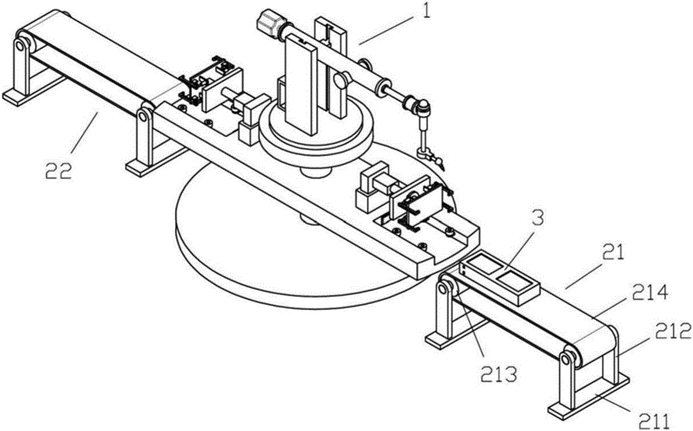
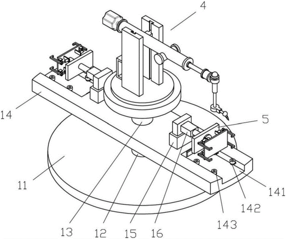
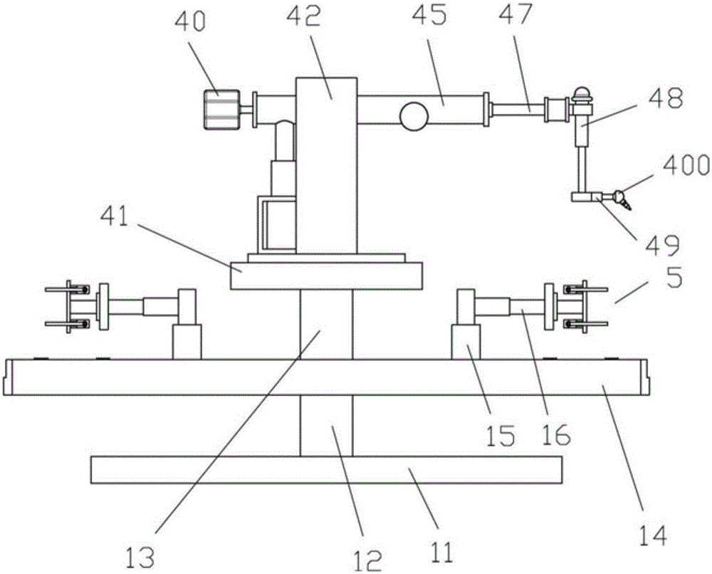
[0025] Such as Figure 1-6 As shown, the ceramic substrate rotary dispenser system includes a feeding device 21, a rotary dispenser 1, a discharging device 22, and a control device. The rotary dispenser 1 is located between the feeding device 21 and the discharging device 22. All are electrically connected to the control device; the rotary dispenser 1 includes a fixed base 11, the upper part of the fixed base 11 is connected to a rotary docking plate 14 through a first rotating shaft 12, and the upper part of the rotary docking plate 14 is connected to a dispenser through a second rotating shaft 13 4; The two ends of the rotating docking plate 14 are provided with grooves 141 for accommodating the material box 3, the t...


PUM


Abstract

The invention discloses a rotating dispenser system for ceramic substrates. The rotating dispenser system comprises a feed device, a rotating dispenser, a discharge device and a control device. The rotating dispenser is located between the feed device and the discharge device. The rotating dispenser, the feed device and the discharge device are all electrically connected with the control device. The rotating dispenser comprises a fixed base. The upper portion of the fixed base is connected with a rotating butt joint plate through a first rotating shaft. The upper portion of the rotating butt joint plate is connected with the dispenser through a second rotating shaft. Grooves containing material boxes are formed in the two ends of the rotating butt joint plate. First guide wheels and second guide wheels are arranged on the two sides of each groove correspondingly. Fixing sleeves are further arranged on the inner sides of the grooves and are sleeved with lifting rods in a telescopic manner. Telescopic rods are fixedly connected with the side faces of the lifting rods. The tail ends of the telescopic rods are fixedly connected with fixing assemblies. The dispenser is the rotating dispenser and is located in a production line to complete connection of feed and discharge, occupied space is saved, rapid dispensing can be achieved, and the rotating dispenser system has the beneficial effects of being capable of saving space, easy to operate, high in flexibility and the like.

Description

[0001] Technical field: [0002] The invention relates to the technical field of ceramic substrate dispensing technology, in particular to a ceramic substrate rotary dispensing machine system. [0003] Background technique: [0004] Ceramic substrate refers to a special process board in which copper foil is directly bonded to the surface of alumina or aluminum nitride ceramic substrate at high temperature. The ultra-thin composite substrate made has excellent electrical insulation properties, high thermal conductivity, excellent solderability and high adhesion strength, and can be etched into various patterns like a PCB board, and has a large current carrying capacity. ability. Therefore, ceramic substrates have become the basic material for high-power power electronic circuit structure technology and interconnection technology. The advent of ceramic substrate products has opened up the development of the heat dissipation application industry. Due to the heat dissipation characteri...

Claims


Application Information

Patent Timeline
Patent Type & Authority Applications(China)
IPC IPC(8): B05C5/02B05C13/02
CPCB05C5/0208B05C13/02
Inventor 叶芳
Owner FOSHAN HUAPU RUILIAN ELECTROMECHANICAL TECH CO LTD
Why Eureka
Try Eureka