
Ribbon spring for sprag-type one-way clutch, and sprag-type one-way clutch

A technology of one-way clutches and wedges, applied in one-way clutches, clutches, gear transmission mechanisms, etc., can solve problems such as abnormal friction, wedge application, peeling, etc., and achieve reliable functions and smooth sliding effects

Inactive Publication Date: 2017-05-17
NTN CORP
View PDF12 Cites 3 Cited by
  • Summary
  • Abstract
  • Description
  • Claims
  • Application Information

AI Technical Summary

Problems solved by technology

When the wedge tilts, the tongue portion of the strip spring slides at the contact portion of the wedge, and if the coefficient of friction at the contact portion is large, smooth sliding properties cannot be obtained, and the tongue portion Damaged by being clamped, there is a possibility of damage at this time
In particular, when the speed at which the sprags are switched from the locked state in which the outer and inner rings are engaged to the idling state in which they are disengaged is high, there is a high possibility that the above-mentioned disadvantages will occur.
[0008] Here, if the tongue portion is damaged, a moment in the direction of contact with the outer ring and the inner ring cannot be applied to the sprag, and when switching from the disengaged state to the engaged state, the sprag engages later than the other sprags. In the state of load, other wedges are engaged with the outer ring and inner ring with high surface pressure, and abnormal wear occurs in the engaging part, and there is a possibility of peeling off
[0009] In addition, when the tongue portion is damaged, there is a possibility that a wedge cannot be engaged to disengage the damaged tongue portion.

Method used


Image

  • Ribbon spring for sprag-type one-way clutch, and sprag-type one-way clutch
  • Ribbon spring for sprag-type one-way clutch, and sprag-type one-way clutch
  • Ribbon spring for sprag-type one-way clutch, and sprag-type one-way clutch

Examples


Embodiment Construction

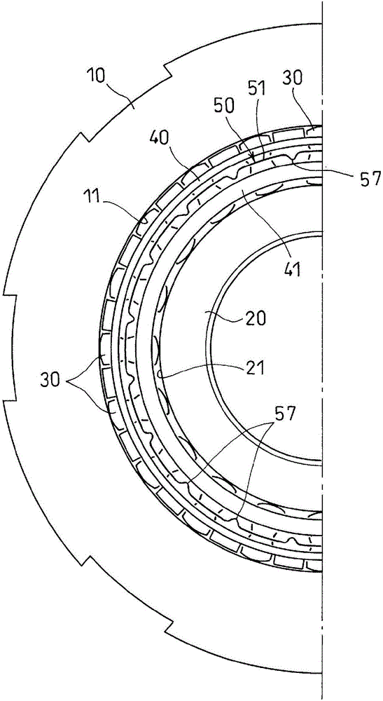
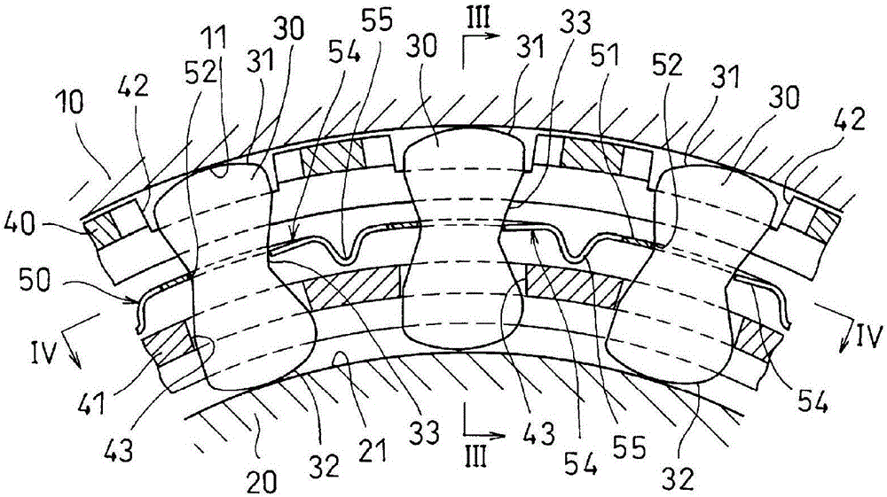
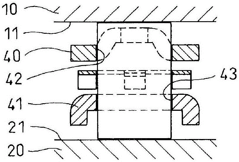
[0026] Hereinafter, embodiments of the present invention will be described based on the drawings. like figure 1 as well as figure 2 As shown, the sprag type one-way clutch has an outer ring 10 and an inner ring 20 assembled inside, and a plurality of sprags 30 are assembled between the outer ring 10 and the inner ring 20 . Further, an outer cage 40 and an inner cage 41 for holding the wedge 30 are assembled between the outer ring 10 and the inner ring 20 , and a belt spring 50 is assembled between the outer cage 40 and the inner cage 41 .

[0027] The inner diameter surface 11 of the outer ring 10 and the outer diameter surface 21 of the inner ring 20 are formed as cylindrical surfaces. The wedge 30 is cocoon-shaped, and one end is provided with an outer ring side cam surface 31 which engages and separates from the inner diameter surface 11 of the outer ring, and the other end is provided with an inner ring side which engages and separates from the outer diameter surface 21...


PUM


Abstract

This invention makes it possible to obtain smooth sliding properties at the contact parts of sprags and tongue parts, which bias the sprags in the direction of engagement, in a sprag-type one-way clutch. A plurality of pockets (52) are formed, at intervals in the length direction of an elongated belt-shaped plate part (51) formed from sheet metal, by punching, which is a type of shearing processing, and tongue parts (54) that protrude inside the pockets (52) are provided on one side of pillar parts (53) formed between adjacent pockets (52) in the peripheral direction. The belt-shaped plate part (51) is bent into a circular shape and installed between an outer ring (10) and an inner ring (20), and the sprags (30), which are respectively inserted into the pockets (52), are biased in the engagement direction by the tongue parts (54). The sliding properties are improved by bending the belt-shaped plate part (51) such that a shear drop (58) formed on the cut edge surface of the sheared edge of the tongue part (54) is on the outer diameter side, and bringing the shear drop (58) into contact with the sprag (30).

Description

technical field [0001] The present invention relates to a band spring of a sprag-type one-way clutch used in a torque converter of an automobile, etc., and a sprag-type one-way clutch using the band spring. Background technique [0002] Such a sprag-type one-way clutch is described, for example, in the following Patent Documents 1 to 3. A plurality of sprags are assembled between the outer ring and the inner ring, and the sprags are passed through an outer cage assembled between the outer ring and the inner ring. And the inner cage is held, through the band spring assembled between the two cages, a plurality of wedges are respectively directed to the outer ring side cam surface and the inner ring side cam surface and the inner diameter surface of the outer ring and the outer ring outer surface of the inner ring. Push in the direction of radial surface contact. [0003] Here, in the strip spring, a plurality of pockets are punched out at intervals in the longitudinal directi...

Claims


Application Information

Patent Timeline
Patent Type & Authority Applications(China)
IPC IPC(8): F16D41/07
CPCF16D41/07F16D2041/0605F16D2250/0023F16D2250/003
Inventor 富加见理之
Owner NTN CORP
Learn More