Eureka AIR delivers breakthrough ideas for toughest innovation challenges, trusted by R&D personnel around the world.

Double-Pipe Heat Exchanger and Manufacturing Method Thereof

a heat exchanger and double-pipe technology, applied in the direction of machines/engines, combustion-air/fuel-air treatment, light and heating apparatus, etc., can solve the problem of high manufacturing cost as a whole, achieve high heat exchange performance, enhance heat exchange performance, and high strength

Inactive Publication Date: 2008-10-16
T RAD CO LTD
View PDF3 Cites 12 Cited by
  • Summary
  • Abstract
  • Description
  • Claims
  • Application Information

AI Technical Summary

Benefits of technology

[0012]The double-pipe heat exchanger and the manufacturing method thereof according to the present invention have such structure and arrangement as described above, and provide the following advantages.
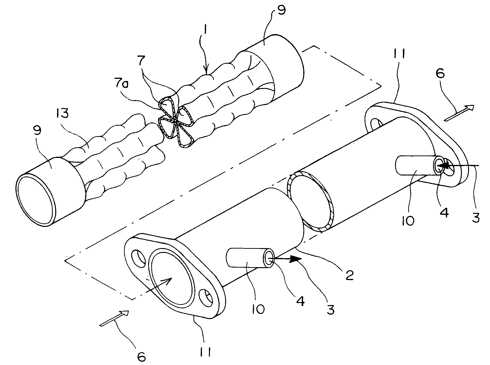
[0014]As a result, particularly with respect to the first fluid 3 flowing between the inner tube 1 and the outer tube 2, high pressure resistance is achieved. That is, even if the first flow path 5 is applied with a large internal pressure, the inner tube 1 is never deformed.
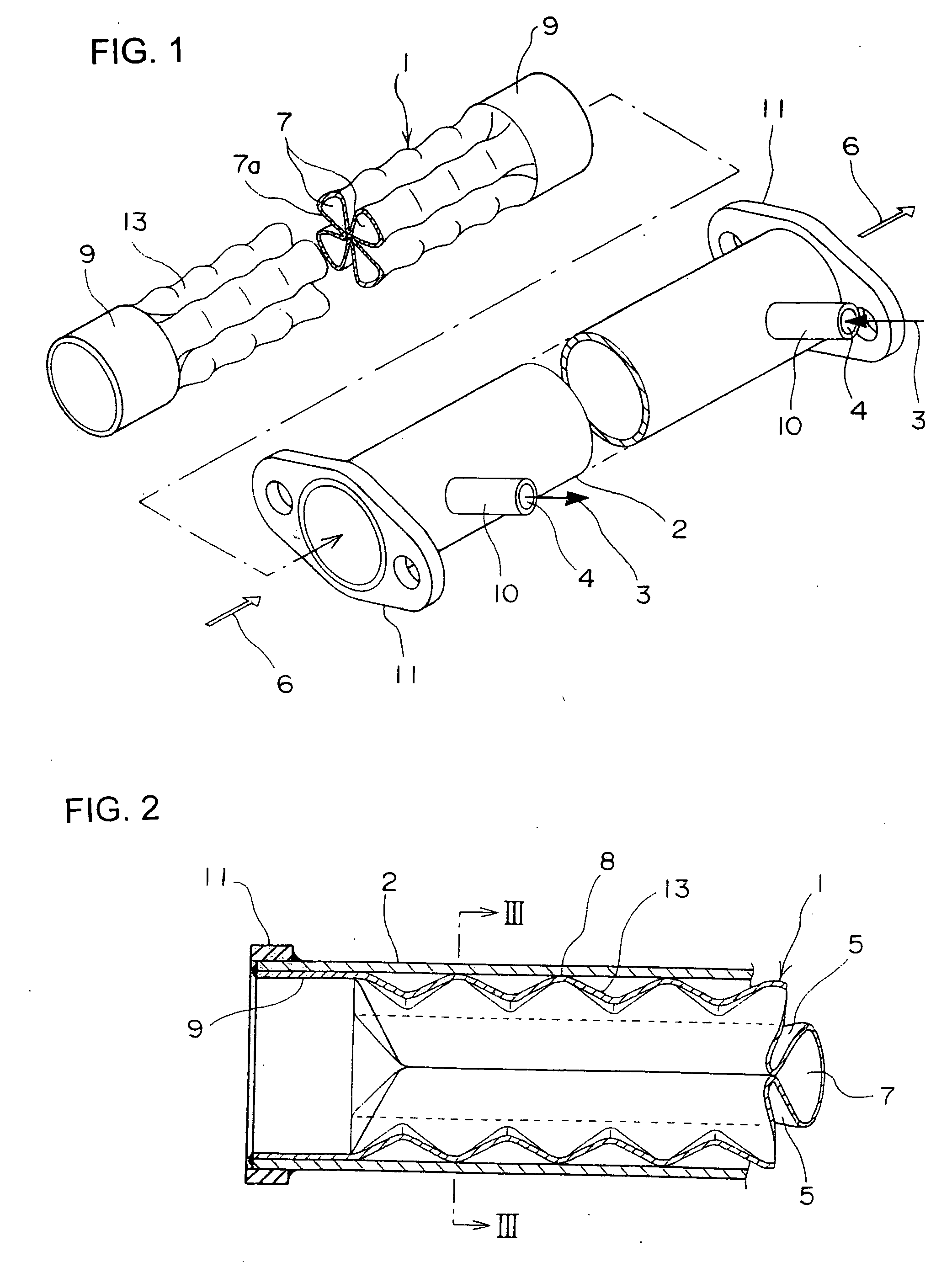
[0015]In the above-mentioned construction, respective swollen portions 7a are bent in a wave shape along an axial direction at the tip end portions, and thus a top portion 8 of these waves can be in contact with the inner circumference of the outer tube 2. In this case, the first fluid 3 and the second fluid 6 are stirred, thus enabling to enhance heat exchange performance, and since the top portions 8 of the inner tube 1 and the inner circumference of the outer tube 2 are in contact, a heat exchanger having high strength as well as high pressure resistance may be achieved.
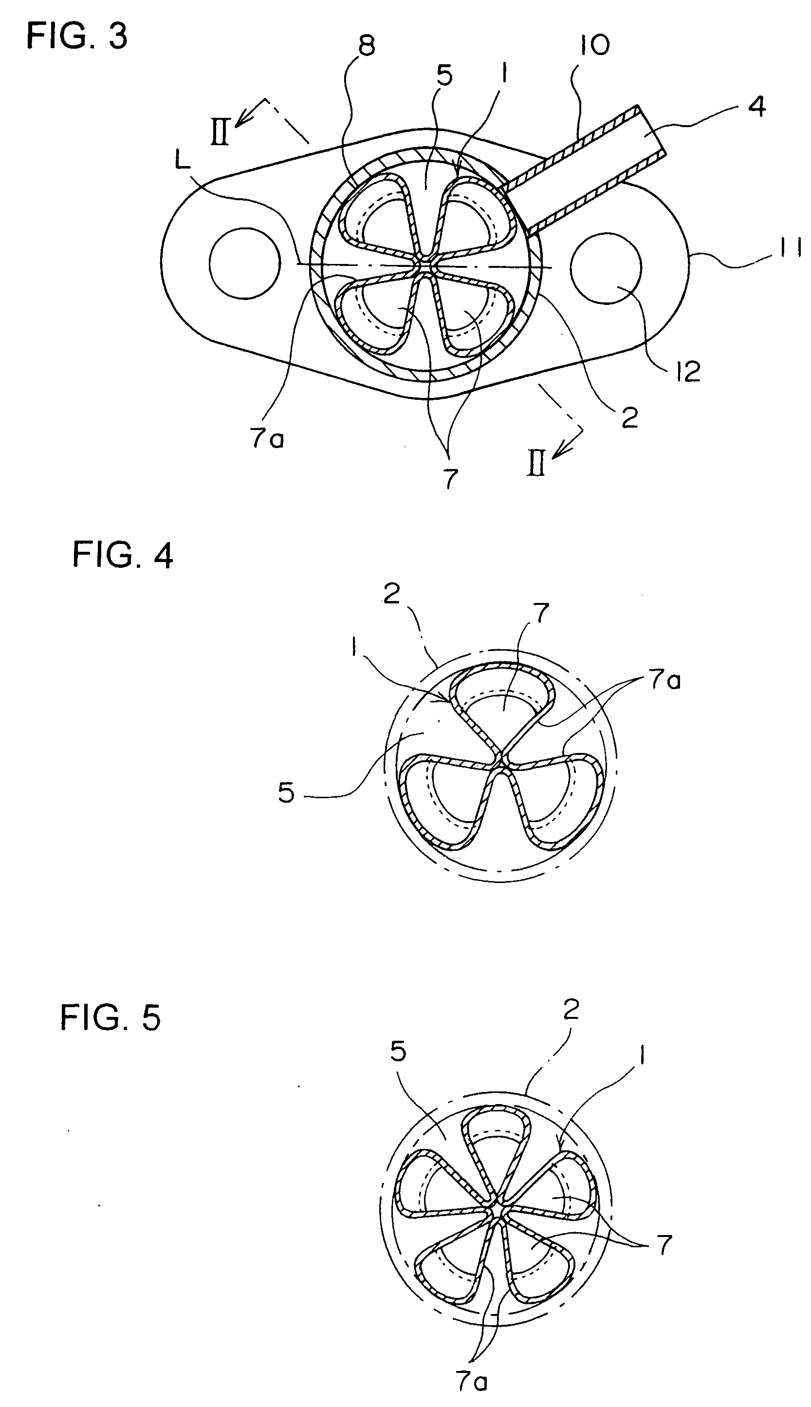
[0016]In the above-mentioned construction, two or more swollen portions 7a may be formed at equal intervals in a circumferential direction of the inner tube 1. Thus, it is possible to cause the first fluid 3 and the second fluid 6 to flow uniformly, as well as to achieve higher-pressure resistance.
[0017]In the manufacturing method of the double-pipe heat exchanger of the above-mentioned construction, in a state that the outer tube 2 is fitted over the outer circumference of the inner tube 1, both tubes can be applied with an external force so that axis lines thereof are bent to deform plastically. The inner tube 1 includes two or more swollen portions 7a protruded in a radial direction form center, these swollen portions 7a being constructed that mouths of bladder-like shapes in section thereof are closed, whereby it is possible to perform an extremely smooth bending of the inner tube 1. That is, there is no fear of the occurrence of deformation such as buckling of the inner tube 1 in the process of bending. In particular, in the case that the outer circumference of the inner tube 1 and the inner circumference of the outer tube 2 are in contact with each other, buckling of both the inner tube 1 and the outer tube 2 does not occur, thus enabling to make forming by bending smoothly.
[0018]In the above-mentioned construction, there is provided in the inner tube 1 an even number of four or more swollen portions 7a uniformly disposed in a circumferential direction, an external force is applied, and both tubes can be deformed by bending with a diameter line L where there is no bladder-like shape in section as a center of curvature. As a result, it is possible to make forming of the inner tube 1 and the outer tube 2 by bending more smoothly.

Problems solved by technology

Therefore, there have been such problems that the EGR cooler lacks flexibility in a position to be disposed, and the number of parts for connection thereof, for example, becomes big, thus inevitably resulting in higher manufacturing costs as a whole.

Method used


Image

  • Double-Pipe Heat Exchanger and Manufacturing Method Thereof
  • Double-Pipe Heat Exchanger and Manufacturing Method Thereof
  • Double-Pipe Heat Exchanger and Manufacturing Method Thereof

Examples


third embodiment

[0035]Next, FIG. 5 shows a laterally sectional view of an inner tube 1 illustrating a heat exchanger according to the present invention, and this example includes five swollen portions 7a formed at equal intervals in the radial direction. Also in this example, mouths of the bladder-like shapes in section of respective swollen portions 7a are closed.

fourth embodiment

[0036]In the next, FIG. 6 shows a laterally sectional view of an inner tube 1 illustrating a fourth embodiment according to the present invention, and this example includes two swollen portions 7a protruded in a diameter direction of an outer tube 2. Also in this example, mouths of the bladder-like shapes in section of respective swollen portions 7a are closed.


PUM


Abstract

A double-pipe heat exchanger that is easy to manufacture, and the whole thereof is smoothly bent to serve as part of the piping, and that provides high pressure resistance, wherein an inner tube has a section orthogonal to an axis line thereof in which a plurality of swollen portions in a bladder-like or balloon-like shape in section are formed in a radial direction from the center, mouths of these swollen portions are closed, and the tip ends of respective swollen portions are in contact with the inner surface of an outer tube.

Description

BACKGROUND OF THE INVENTION[0001]The present invention relates to a double-pipe heat exchanger for use as an EGR cooler, an oil cooler, or the like, the double-pipe heat exchanger being capable of smoothly bending along a pipeline of vehicles.[0002]An EGR cooler is interposed on the way of piping of exhaust gas of an engine, and acts to cool the exhaust gas using cooling water. This EGR cooler is exemplified as below by a double-pipe heat exchanger disclosed in Japanese Patent Application Laid-open No. 2000-161871.[0003]This double-pipe heat exchanger is in a double-pipe structure with an inner tube and an outer tube, in which structure a radiator fin is integrally formed by bending at the intermediate portion in an axial direction of the inner tube. That is, the inner tube has at the intermediate portion a multiple number of protrusions formed in a radial direction from the center in section thereof.[0004]Conventionally, an EGR cooler is interposed at the linear portion on the way ...

Claims


Application Information

Patent Timeline
Patent Type & Authority Applications(United States)
IPC IPC(8): F28D7/10F02M25/07F28D7/16F28F1/02F28F1/06F28F1/08
CPCF02M25/0737F28D7/106F28F1/022F28F1/06F28F1/08Y02T10/121F02M26/32
Inventor YUSA, KAZUHIKO
Owner T RAD CO LTD
Why Eureka
Eureka Blog
Learn More