Water cooling device for electric vehicle charger

A water-cooling device and charger technology, applied in battery circuit devices, electric vehicles, circuit devices, etc., can solve the problems of damage to circuit components, decrease in heat dissipation efficiency, aging, etc., and achieve solutions to aging damage, simple structure, and improved efficiency. Effect

Inactive Publication Date: 2017-05-17
岑利娜
View PDF0 Cites 1 Cited by
  • Summary
  • Abstract
  • Description
  • Claims
  • Application Information

AI Technical Summary

Problems solved by technology

However, the above method has the following problems: In order to achieve the heat dissipation effect, the conventional heat sink has a large volume, and its heat dissipation path is to conduct the heat on the printed circuit board to the internal space of the charger through the heat sink, and through the radiation effect from the hole in the shell. out, or through secondary conduction to the metal casing, and then radiate to the outside space
On the one hand, this heat dissipation method lengthens the heat dissipation path (conduction-radiation-conduction-radiation), which reduces the heat dissipation efficiency. In addition, through the first conduction of the heat sink, a large amount of heat is radiated and accumulated in the inner space of the charger, making the The components on the entire circuit board are shrouded in high heat, which will also accelerate the aging of components. Although there are cooling holes, the waterproof and dustproof effect of this structure is low, which will easily lead to damage and aging of circuit components. To meet the increasingly common outdoor use environment, moreover, in order to achieve a better effect, more fins need to be set to increase the heat dissipation area, which also increases the cost
Based on the above reasons, the repair rate and scrap rate of chargers remain high, which brings great troubles to merchants and consumers.

Method used


Image

  • Water cooling device for electric vehicle charger

Examples


Embodiment Construction

[0010] The following will clearly and completely describe the technical solutions in the embodiments of the present invention with reference to the accompanying drawings in the embodiments of the present invention. Obviously, the described embodiments are only some, not all, embodiments of the present invention. Based on the embodiments of the present invention, all other embodiments obtained by persons of ordinary skill in the art without making creative efforts belong to the protection scope of the present invention.

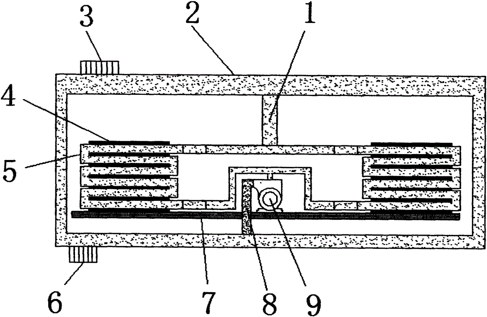
[0011] see figure 1 , the present invention provides a technical solution: a water cooling device for an electric vehicle charger, comprising a housing 2 and a heat sink 4, the upper left side of the housing 2 is fixedly connected with a water inlet 3, and the lower left side of the housing 2 The water outlet 6 is fixedly connected, and by setting the water inlet 3 and the water outlet 6, it is convenient to change and replenish the water of the heat sink afte...


PUM


Abstract

The invention discloses a water cooling device for an electric vehicle charger, which comprises a shell and cooling fins, and is characterized in that the upper part of the left side of the shell is fixedly connected with a water inlet, the lower part of the left side of the shell is fixedly connected with a water outlet, the lower part of an inner cavity of the shell is fixedly provided with a circuit board, the middle part of the circuit board is fixedly connected with a water pump, the left side of the water pump is fixedly connected with the bottom part of the shell through a water pipe, the bottom parts of the cooling fins are fixedly connected with the circuit board, the upper part of the water pump is fixedly connected with a heat absorbing pipe through a water pipe, the heat absorbing pipe is distributed at the outer sides of the cooling fins in an S-shaped manner, and the upper end of the heat absorbing pipe is fixedly connected with the upper part of the shell through a water outlet pipe. The water cooling device is simple in structure, convenient and practical, effectively performs cooling on the electric vehicle charger, protects a mainboard of the charger from being damaged and prolongs the service life of the charger.

Description

technical field [0001] The invention relates to the technical field of electronic equipment, in particular to a water cooling device for an electric vehicle charger. Background technique [0002] The heat dissipation of the charger has always been one of the technical problems to be solved by the charger, especially the electric vehicle charger. Currently, the chargers on the market generally adopt a metal radiator installed on the printed circuit board. Or choose a metal shell with good heat dissipation effect, or set heat dissipation holes in the charger shell to achieve heat dissipation. However, the above method has the following problems: In order to achieve the heat dissipation effect, the conventional heat sink has a large volume, and its heat dissipation path is to conduct the heat on the printed circuit board to the internal space of the charger through the heat sink, and through the radiation effect from the hole in the shell. out, or through secondary conduction ...

Claims


Application Information

Patent Timeline
Patent Type & Authority Applications(China)
IPC IPC(8): H02J7/00H05K7/20
Inventor 岑利娜
Owner 岑利娜
Why Eureka
Try Eureka