
Target material device

A target and fixing ring technology, applied in electrical components, semiconductor/solid-state device manufacturing, circuits, etc., can solve problems such as rising production costs, damage to the structure of connectors, easy splashing, etc., to improve product shipment yield, prevent The effect of being burned by electric shock and reducing production costs

Active Publication Date: 2017-05-17
HKC CORP LTD +1
View PDF8 Cites 0 Cited by
  • Summary
  • Abstract
  • Description
  • Claims
  • Application Information

AI Technical Summary

Problems solved by technology

However, in the process of magnetron sputtering target coating substrate, the substances formed during the sputtering process are easy to splash on the connectors at the bottom of the target, destroying the structure of the connectors and reducing the service life of the connectors, resulting in a significant increase in production costs. rise
At the same time, the polyetheretherketone (peek) fittings on the connectors at the bottom of the ITO target are exposed to the air and are easily burned by electric shocks. The burned connectors are likely to cause abnormal shutdown of the production equipment, and new connectors need to be replaced. Restarting work will result in loss of production capacity and waste of time, manpower, materials, etc., greatly affecting the yield of product shipments

Method used


Image

  • Target material device
  • Target material device
  • Target material device

Examples


Embodiment Construction

[0012] The following will clearly and completely describe the technical solutions in the embodiments of the present invention with reference to the accompanying drawings in the embodiments of the present invention. Obviously, the described embodiments are some of the embodiments of the present invention, but not all of them. Based on the embodiments of the present invention, all other embodiments obtained by persons of ordinary skill in the art without making creative efforts belong to the protection scope of the present invention.

[0013] It should be understood that when used in this specification and the appended claims, the terms "comprising" and "comprises" indicate the presence of described features, integers, steps, operations, elements and / or components, but do not exclude one or Presence or addition of multiple other features, integers, steps, operations, elements, components and / or collections thereof.

[0014] It should also be understood that the terminology used ...


PUM


Abstract

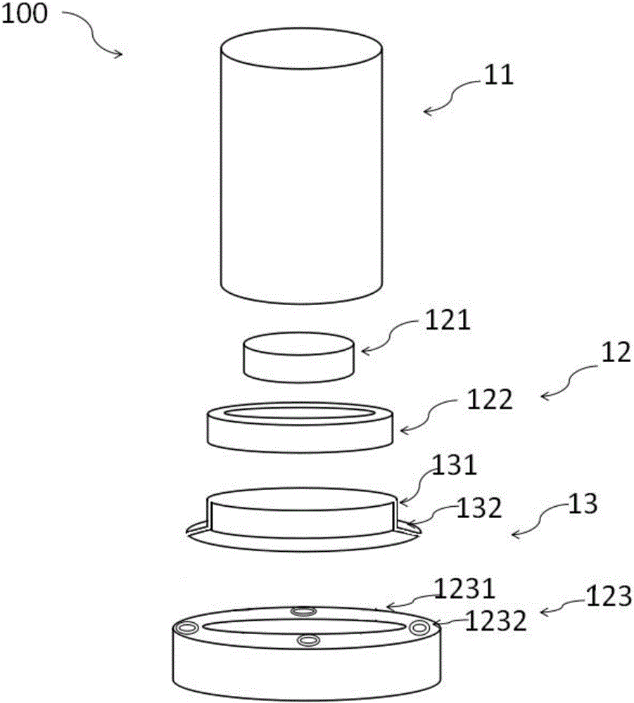
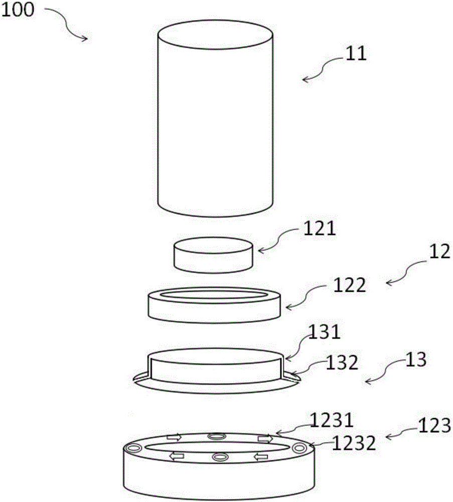
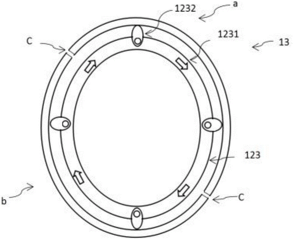
The embodiment of the invention discloses a target material device. The target material device is provided with a connecting piece and a protective plate, wherein the connecting piece comprises a supporting ring and a fixed ring, and multiple ceramic connecting piece accessories are arranged on the fixed ring at intervals; the protective plate comprises a bottom and a top formed by extending from the bottom, the top is hollow, the bottom is supported by the connecting piece accessories and covers one end face of the fixed ring, and the inner circumferential face, extending from the bottom, of the top encircles the end face, away from the fixed ring, of the supporting ring. The target material device has the advantages that the connecting piece structure exposed outside is placed into the protective plate to be protected, the protective plate is capable of protecting the connecting piece structure exposed outside from sputter of substances formed during target material sputtering coating to prevent the connecting piece from being damaged, and the service life of the connecting piece is prolonged. The substances sputtered on the protective plate are washed away easily, so that the use ratio of the connecting piece and the protective plate is increased, and the production cost is greatly reduced.

Description

technical field [0001] The invention relates to the technical field of display processing, in particular to a target device. Background technique [0002] Thin film transistor liquid crystal display (TFT-LCD) is composed of a thin film transistor (TFT) array substrate and a color filter (CF) substrate. Among them, during the fabrication process of the CF substrate, it is necessary to deposit a layer of indium tin oxide (ITO) thin film on the CF substrate by magnetron sputtering or evaporation coating. ITO thin film has excellent conductivity and visible light transmittance, and is an important transparent conductive film. At present, magnetron sputtering technology is generally used to prepare ITO thin film on CF substrate. The principle of preparing ITO thin films by magnetron sputtering technology is to realize plasma discharge under vacuum conditions, use electromagnetic field to control the movement of charged particles, bombard the ITO target, and the ITO target atoms ...

Claims


Application Information

Patent Timeline
Patent Type & Authority Applications(China)
IPC IPC(8): H01L21/263H01L21/67
CPCH01L21/2633H01L21/67063
Inventor 朱桔源
Owner HKC CORP LTD
Learn More