Single-mode fiber birefringence measurement device and method
A single-mode optical fiber and birefringence technology, which is applied in the direction of measuring devices, optical instrument testing, testing optical fiber/optical waveguide equipment, etc., can solve the problems of expensive polarization analysis instruments, complex signal demodulation equipment, and restrictions on wide application, etc., to achieve The effect of simple structure, good application prospect and high measurement accuracy
- Summary
- Abstract
- Description
- Claims
- Application Information
AI Technical Summary
Problems solved by technology
Method used
Image


Examples
specific Embodiment approach 1
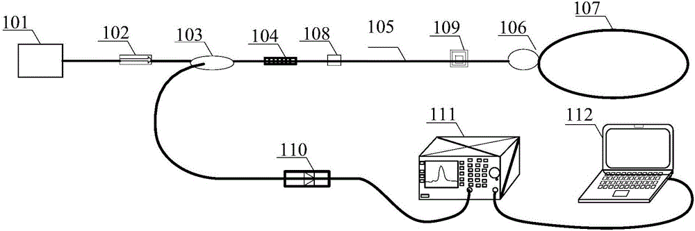
[0022] Specific implementation mode 1. Combination figure 1 Describe this embodiment, a device for measuring the birefringence of a single-mode optical fiber described in this embodiment, which includes a pump light source, an optical isolator, a wavelength division multiplexer, a ring cavity fiber laser, a photodetector, and a spectrum acquisition module and data processing module; the ring cavity fiber laser includes fiber grating, erbium-doped fiber, fiber coupler, fiber ring structure, fixed platform and variable micro-displacement platform;
[0023] The optical signal of the pump light source passes through the optical fiber through the optical isolator to eliminate the reflected light and then transmits to the optical signal input end of the wavelength division multiplexer through the optical fiber. The optical signal output end of the wavelength division multiplexer is connected to one end of the fiber grating, and the grating fiber The other end of (104) is connected ...
specific Embodiment approach 2
[0025] Specific embodiment two, a kind of method for measuring the birefringence of single-mode optical fiber described in the present embodiment, the concrete steps of this method are:
[0026] Step 1, using the pumping light source to send the pumping light signal to the wavelength division multiplexer through the optical fiber, and the optical signal is input to the optical fiber ring structure through the optical fiber coupler after passing through the optical fiber grating and the erbium-doped optical fiber;
[0027] Step 2. Use the fixed platform to fix one end of the erbium-doped fiber, and use a variable micro-displacement platform to achieve axial stretching of the erbium-doped fiber, so that the length of the erbium-doped fiber, the effective refractive index of the laser mode and the birefringence of the fiber Produce changes; obtain laser signals with birefringence changes;
[0028] Step 3: Use the optical fiber ring structure to reflect the incoming optical signal...
specific Embodiment approach 3
[0031] Specific embodiment three. This embodiment is a further description of a method for measuring the birefringence of a single-mode optical fiber described in the second specific embodiment. The specific method for obtaining the birefringence information of the optical fiber caused by the axial strain described in step five is as follows: :
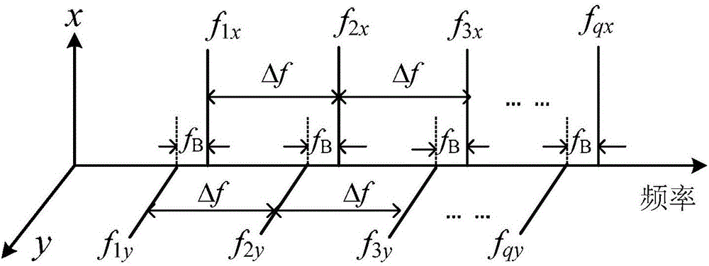
[0032] Step 51. According to the laser mode theory, the frequency of the qth order longitudinal mode signal in the ring cavity fiber laser is obtained; the frequency of the qth order longitudinal mode signal in the ring cavity fiber laser is expressed as:
[0033] f=qc / (nL) (1)
[0034] Among them, q is the order of the laser longitudinal mode, c is the speed of light propagation in vacuum, n is the effective refractive index of the laser mode, and L is the effective cavity length of the ring cavity fiber laser;
[0035] Step 52: After the multi-longitudinal mode laser output by the ring cavity fiber laser is detected by the photodet...
PUM
 Abstract
Description
Claims
Application Information
 - R&D
- Intellectual Property
- Life Sciences
- Materials
- Tech Scout
- Unparalleled Data Quality
- Higher Quality Content
- 60% Fewer Hallucinations
Browse by: Latest US Patents, China's latest patents, Technical Efficacy Thesaurus, Application Domain, Technology Topic, Popular Technical Reports.
© 2025 PatSnap. All rights reserved.Legal|Privacy policy|Modern Slavery Act Transparency Statement|Sitemap|About US| Contact US: help@patsnap.com