
System for improving LNG yield of methane cryogenic separation

A cryogenic separation and methane technology, which is applied in the system field of improving the LNG yield of methane cryogenic separation, can solve the problems of increased synthesis compressor power, increased discharge of purge gas, and decreased LNG production, so as to reduce exhaust emissions , increase production, reduce the effect of formaldehyde content

Inactive Publication Date: 2017-05-17
查都(海南)科技有限公司
View PDF8 Cites 1 Cited by
  • Summary
  • Abstract
  • Description
  • Claims
  • Application Information

AI Technical Summary

Problems solved by technology

[0007] With the increase of the load of the methane cryogenic separation device and the influence of the summer temperature rise, the temperature of the methane raw material gas and the mixed refrigerant entering the cold box cannot be lowered in the actual production process, and the cooling effect of the system is poor, and the cooling capacity is insufficient, which makes the rectification The methane content of the gas coming out of the top of the tower is too high, which does not meet the design requirements, resulting in a decrease in the LNG yield and LNG output
At the same time, the content of inert gas entering the synthesis process is relatively high, the power of the synthesis compressor increases, the discharge of purge gas increases, and the reaction efficiency decreases, which not only pollutes the environment, but also affects the methanol production.

Method used


Image

  • System for improving LNG yield of methane cryogenic separation
  • System for improving LNG yield of methane cryogenic separation
  • System for improving LNG yield of methane cryogenic separation

Examples


Embodiment Construction

[0026] The Examples described below illustrate the present invention in detail, but the present invention is not limited to the following Examples. The preferred embodiments of the present invention will be described in detail below in conjunction with the accompanying drawings, so that the advantages and features of the present invention can be more easily understood by those skilled in the art, so as to define the protection scope of the present invention more clearly.

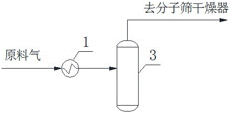
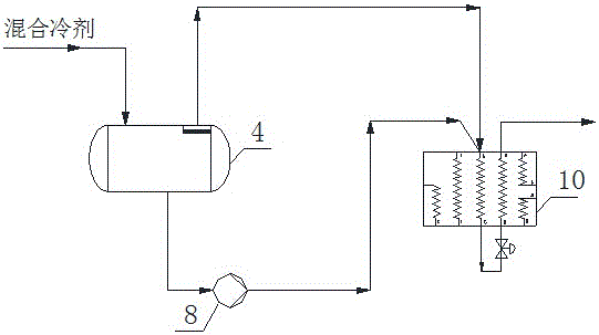
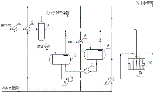
[0027] Such as image 3 A system for improving the yield of methane cryogenic separation of LNG is shown, including a feed gas compression system and a mixed refrigerant circulation system. The feed gas compression system is connected to the compressor outlet cooler 1 inlet through a pipeline, and the compressor outlet is cooled. The outlet of the device 1 is connected to the raw gas inlet chilled water heat exchanger 2, the outlet of the raw gas inlet chilled water heat exchanger 2 is connected to the inlet...


PUM


Abstract

The invention provides a system for improving the LNG yield of methane cryogenic separation. According to the system, cold water at 5-10 DEG C of a chilled water pipe network is mainly used for inputting cooling capacity to a raw gas compression system and a mixed refrigerant circulation system for methane cryogenic separation. The purposes of optimizing the operation conditions of a methane rectifying column and improving separation efficiency are realized by lowering the temperature of raw methane gas and mixed refrigerants, and therefore the content of formaldehyde in column top gas is reduced, and the LNG yield is improved. Particularly, a chilled water heat exchanger is added before the raw gas enters a molecular sieve, and two chilled water heat exchangers are added correspondingly before a gas phase pipeline and a liquid phase pipeline of a refrigerant compressor outlet separation tank enter a cold box. The system improves the LNG yield of methane cryogenic separation, effectively increases the output of LNG, brings considerable economic benefits for enterprises, and is simple in process, convenient to operate and low in daily maintenance cost.

Description

technical field [0001] The invention relates to a methane cryogenic separation device, in particular to a system for improving the yield of methane cryogenic separation LNG. Background technique [0002] The cryogenic separation of methane is mainly to use the different boiling points of the components in the raw gas to achieve the purpose of separating methane through physical cooling. The device first compresses the raw material gas and enters the molecular sieve to remove the trace amount of methanol and water, and then enters the cold box and passes through the plate-fin heat exchanger to cool to -157°C. At this time, a large amount of methane is condensed, and the gas passes through the rectification tower. After evaporation and condensation, the methane in the raw gas is separated, the liquid methane product from the bottom of the rectification tower is sent to the LNG storage tank, and the hydrogen and carbon monoxide from the top of the rectification tower enter the ...

Claims


Application Information

Patent Timeline
IPC IPC(8): F25J3/02F25J5/00
CPCF25J3/0233F25J5/00F25J2205/84F25J2215/60F25J1/0022F25J1/0052F25J1/0212F25J1/0291F25J1/0297
Inventor 刘新波孙乃良杨延奇高向国蔡鹏张一可马海艳
Owner 查都(海南)科技有限公司
Learn More