
Engine piston capable of saving energy and prolonging service life

A technology for engines and pistons, applied to engine components, machines/engines, pistons, etc., to prevent cylinder scuffing, improve lubrication conditions, and reduce frictional resistance

Active Publication Date: 2017-05-17
CHANGCHUN INST OF TECH +1
View PDF17 Cites 3 Cited by
  • Summary
  • Abstract
  • Description
  • Claims
  • Application Information

AI Technical Summary

Problems solved by technology

The stress on the piston skirt gradually increases from top to bottom, first decreases and then increases from the middle to both sides. This is because the upper end of the skirt is closer to the ring groove and the stress is dispersed and transferred to the ring groove. Although the temperature at the lower end of the skirt is the lowest, the stress here The wall thickness is thinner and there is no rib design, and the part of the skirt with a greater stress in the circumferential direction is closest to the pin hole with the largest stress in the full piston, so it bears a greater load. Although the three piston designs mentioned in the prior art can be used in To a certain extent, the above-mentioned technical problems are solved, but there are still deficiencies in ensuring the prolongation of piston fatigue life and fuel saving. Considering the huge engine usage, even if the friction loss of the piston-cylinder liner system is reduced to a small extent, it can also Great impact on reducing energy consumption and improving the environment

Method used


Image

  • Engine piston capable of saving energy and prolonging service life
  • Engine piston capable of saving energy and prolonging service life
  • Engine piston capable of saving energy and prolonging service life

Examples


Embodiment Construction

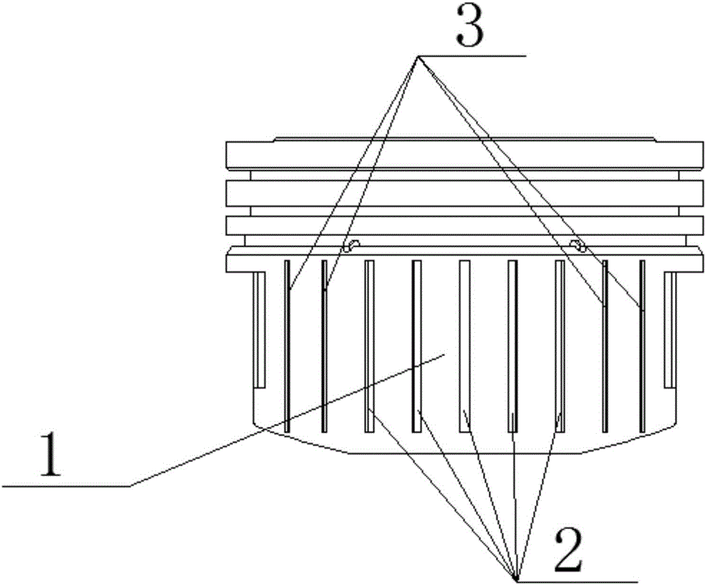
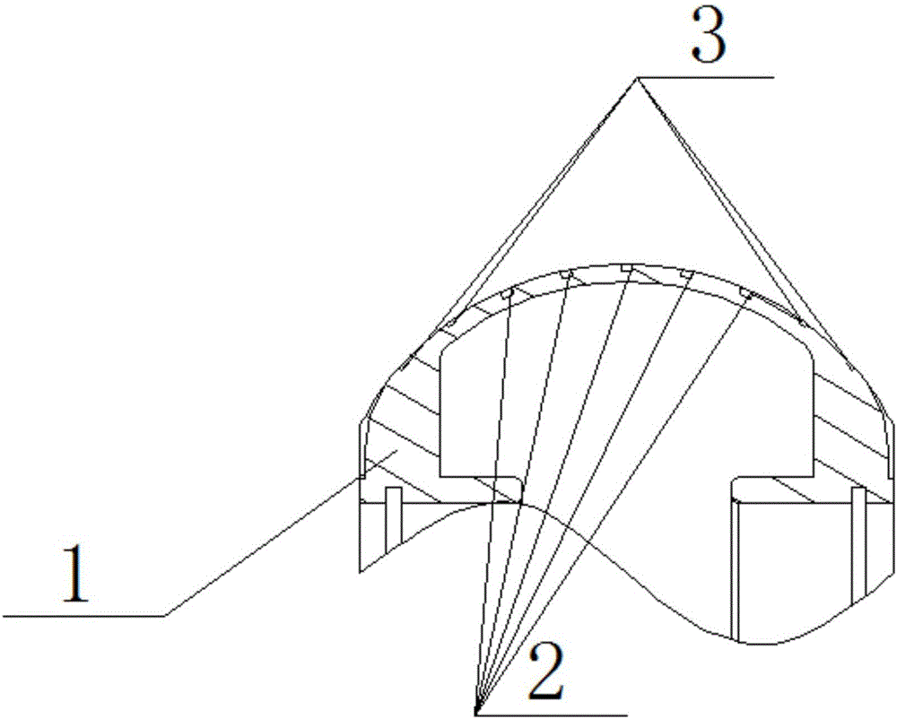
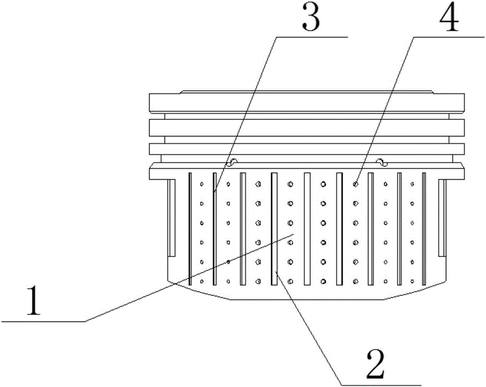
[0033] Such as figure 1 , figure 2 , Figure 5 , Figure 6 and Figure 7As shown, in the present invention, vertical concave stripes parallel to each other are evenly arranged at equal intervals on the outer surface of the piston skirt 1, and the vertical concave stripes include the first vertical concave stripes 2 and the second vertical concave stripes. Stripe 3, the first vertical concave stripe 2 with equal depth is designed on the part of piston skirt 1 with less stress, and the second vertical concave stripe 2 is designed on the part of piston skirt 1 with higher stress 3. The second vertical concave stripe 3 is deeper from the top end of the piston and shallower from the bottom end of the piston. The depth changes linearly from the upper part to the lower part of the piston skirt 1, and the linear relationship is Y=-X(H1-H0) / L3, X and Y are the abscissa and ordinate of the point in the plane respectively, H1 is the groove depth of the top end of the piston, H1 is ...


PUM


Abstract

The invention relates to an engine piston, in particular to an engine piston capable of saving energy and prolonging service life based on lubrication improvement, wear resistance and service life prolonging functions. A skirt portion of the piston is divided into a main stress bearing area and a secondary stress bearing area. Parallel vertical indent stripes are evenly distributed on the outer surface of the skirt portion of the piston at equal intervals. The vertical indent stripes comprise first vertical indent stripes and second vertical indent stripes, the first vertical indent stripes are located in the secondary stress bearing area and are of an equally-wide equally-deep groove structure, the second vertical indent stripes are located in the main stress bearing area and are of an equally-wide unequally-deep groove structure, the depths of the second vertical indent stripes are linearly and progressively decreased from the upper portion to the lower portion of the skirt portion of the piston, the vertical indent stripes can store lubrication oil and abrasive dust, lubrication oil can be sufficiently supplied when the piston does reciprocating motion in a cylinder sleeve, distribution is uniform, friction heat is dispersed, the lubrication effect is improved, friction resistance is reduced, piston scraping and piston slap are prevented, and the service life of the piston and the service life of an air cylinder are prolonged.

Description

technical field [0001] The invention relates to an engine piston, in particular to an energy-saving and life-prolonging engine piston based on the functions of lubricating, wear-resisting and life-prolonging, which can be applied to various engines such as gasoline engines and diesel engines. Background technique [0002] Automobiles have become an indispensable means of walking, transportation and transportation in people's daily life. Under the current global background of energy saving, emission reduction, haze control and anti-pollution, the development and promotion of new energy vehicles has become the top priority, but it will take some time for its incomplete supporting facilities and high prices to make it popular. The engine is the power source of the car and the main source of harmful exhaust emissions from the car. Many studies have proved that 10% to 20% of the engine combustion energy is consumed in mechanical losses, and 45% to 65% of the energy in mechanical...

Claims


Application Information

Patent Timeline
IPC IPC(8): F02F3/00
CPCF02F3/00Y02T10/12
Inventor 吴波杨利王大宇王洪臣金绍江王征刘旦伊延吉
Owner CHANGCHUN INST OF TECH
Learn More