Multi-stage cyclone dehydration device

A technology of dehydration device and cyclone, which is applied to the separation of dispersed particles, chemical instruments and methods, separation methods, etc., can solve the problems of large maintenance workload and cost, low dehydration efficiency, and large equipment, so as to reduce the waste of water resources and structure Simple, low drag effect

Inactive Publication Date: 2017-05-17
BERIS ENG & RES CORP
View PDF6 Cites 5 Cited by
  • Summary
  • Abstract
  • Description
  • Claims
  • Application Information

AI Technical Summary

Problems solved by technology

At present, dehydration mainly adopts the method of damping dehydration by using fillers or large-space settlement dehydration. Among them, the first method has relatively large resistance, and the maintenance workload and cost are large. The second method has huge equipment, occupies a large area, and requires a large investment. Low dehydration efficiency

Method used


Image

  • Multi-stage cyclone dehydration device
  • Multi-stage cyclone dehydration device

Examples


Embodiment Construction

[0018] Embodiments of the technical solutions of the present invention will be described in detail below in conjunction with the accompanying drawings. The following examples are only used to illustrate the technical solutions of the present invention more clearly, and therefore are only examples, rather than limiting the protection scope of the present invention.

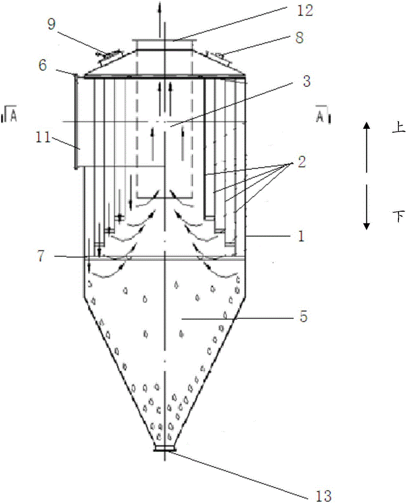
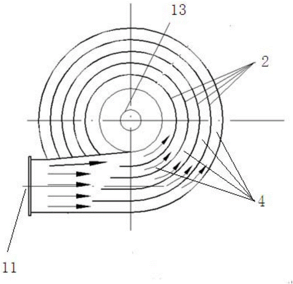
[0019] figure 1 A schematic structural view of a multi-stage cyclone dehydration device according to Embodiment 1 of the present invention is shown; figure 2 is along figure 1 Sectional view of line A-A. Such as figure 1 and figure 2 As shown, the multi-stage cyclone dehydration device includes a cylinder body 1, an air inlet 11 disposed on the side wall of the cylinder body 1, an air outlet 12 disposed on the top of the cylinder body 1, and an air outlet 12 disposed on the bottom of the cylinder body 1. The water outlet 13, and the core tube 3 arranged in the cylinder body 1 and the curved partition 2 surro...


PUM


Abstract

The invention relates to a multi-stage cyclone dehydration device which comprises a barrel, an air inlet formed in the side wall of the barrel, an air outlet formed in the top of the barrel, a water outlet formed in the bottom of the barrel, a core tube arranged in the barrel and a curved baffle plate surrounding the periphery of the core tube, wherein the curved baffle plate limits a spiral flow channel surrounding the outside of the core tube in an upper area in the barrel, and limits a liquid collecting cavity in a lower area in the barrel; the spiral flow channel is connected with the air inlet; the core tube is connected with the air outlet; the liquid collecting cavity is connected with the water outlet; and when a gas carrying a liquid enters the inside of the spiral flow channel from the air inlet, the gas rotates and enters the liquid collecting cavity under the action of the spiral flow channel, the liquid is separated from the gas under the action of centrifugal force and flows outside through the water outlet, and the gas enters the core tube and flows outside from the air outlet. The multi-stage cyclone dehydration device is capable of carrying out efficient dehydration on the gas carrying the liquid in a wet dust removal system, and is low in resistance and high in dust removal efficiency.

Description

technical field [0001] The invention relates to a dehydration device, in particular to a multistage cyclone dehydration device capable of separating water and air in a wet dust removal system. Background technique [0002] Wet purification systems such as converter primary flue gas wet purification system and wet desulfurization system must undergo dehydration treatment before the tail gas is discharged. The main function is to separate the water vapor attached to the dust from the flue gas for effective dehydration, thereby To improve purification efficiency, the second is to reduce water vapor emissions and waste of water resources. At present, dehydration mainly adopts the method of damping dehydration by using fillers or large-space settlement dehydration. Among them, the first method has relatively large resistance, and the maintenance workload and cost are large. The second method has huge equipment, occupies a large area, and requires a large investment. The dehydrat...

Claims


Application Information

Patent Timeline
Patent Type & Authority Applications(China)
IPC IPC(8): B01D45/16
CPCB01D45/16
Inventor 张如海
Owner BERIS ENG & RES CORP
Why Eureka
Try Eureka