
Wireless charging coil alignment method, wireless charging device and charging method of unmanned aerial vehicle

A wireless charging and drone technology, applied in the fields of wireless charging devices, drone charging, and wireless charging coil alignment, can solve the problems of not being able to find the best charging position at one time, limited battery life, short battery life, etc. Guaranteed wireless charging efficiency, accurate alignment, and fast alignment

Active Publication Date: 2017-05-10
HUNAN INST OF TECH
View PDF6 Cites 11 Cited by
  • Summary
  • Abstract
  • Description
  • Claims
  • Application Information

AI Technical Summary

Problems solved by technology

In fact, there is a certain degree of blindness in such a coil automatic alignment method, because it cannot find the best charging position at one time, but continuously moves to the first position corresponding to the maximum current data in the current state during the movement, but the coil In the process of moving to the first position, a larger current may appear again, and a new first position appears at this time, so that the best charging position can be determined after repeated updates. In the end, a higher charging efficiency can be guaranteed, but it still has the disadvantage that the alignment process takes a long time
[0005] In recent years, the consumer drone market has been extremely hot, and the short battery life is a common problem of consumer drones. Consumer drones need to replace batteries or recharge after 20-30 minutes of continuous flight, and drones perform tasks independently. The capability of the task is severely limited by the endurance. Most of the current solutions are to set up electromagnetic induction wireless charging platforms on the flight route. However, these wireless charging platforms also have the problem of being difficult to quickly realize the accurate alignment of the power transmitting coil and the power receiving coil. , so the current wireless charging solutions for drones generally have the disadvantages of low charging efficiency or long time-consuming coil alignment

Method used


Image

  • Wireless charging coil alignment method, wireless charging device and charging method of unmanned aerial vehicle
  • Wireless charging coil alignment method, wireless charging device and charging method of unmanned aerial vehicle

Examples


Embodiment 1

[0036] A wireless charging coil alignment method includes the following steps:

[0037] Set the touch panel above the power transmission coil and determine the initial orthographic projection position of the power transmission coil on the touch panel;

[0038] Touch the touch panel with more than three touch elements that have a fixed positional relationship with the power receiving coil to obtain the position of each touch element and the touch panel contact point;

[0039] Calculating the orthographic projection position of the power receiving coil on the touch panel according to the position of the contact point of each touch element and the touch panel and the positional relationship between the power receiving coil and each touch element;

[0040] The power transmission coil and / or the power reception coil are moved so that the power transmission coil and the power reception coil overlap at the orthographic projection position of the touch panel, thereby completing the alignment o...

Embodiment 2

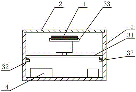
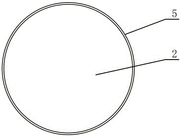
[0044] Based on the coil alignment method in Example 1, see Figure 1-2 As shown, this embodiment provides a wireless charging device, which includes a power transmission coil 1, a touch panel 2, a driving device for driving the power transmission coil 1 and / or the touch panel 2 to move in a plane, and a pair of driving devices The controller 4 that controls, the initial orthographic projection position information of the power transmission coil 1 on the touch panel 2 is stored in the controller 4;

[0045] The touch panel 2 is used to accept the power receiving equipment, accept the touch of more than three touch parts of the power receiving equipment, and send the touch information to the controller 4;

[0046] The controller 4 is used to calculate the position of the contact point of each touch element of the power receiving device with the touch panel 2 according to the above touch information, and then calculate the position relationship between the power receiving coil of the...

Embodiment 3

[0053] On the basis of the foregoing embodiments 1 and 2, the present invention also provides a drone charging method. Specifically, this embodiment uses the wireless charging device described in any one of claims 3-7 to provide The battery of the aircraft replenishes the power, and the drone involved in the charging has more than three supporting legs;

[0054] The drone lands on the touch panel 2. The touch panel 2 accepts the touch of more than three supporting legs of the drone and sends the touch information to the controller 4. The controller 4 calculates that there is no one based on the touch information. The position of the contact points between the support legs of the aircraft and the touch panel 2 is combined with the position relationship between the power receiving coil 1 of the drone and the support legs to calculate the orthographic projection position of the power receiving coil on the touch panel 2, and then control The driving device drives the power transmitti...


PUM


Abstract

The invention provides a wireless charging coil alignment method, a wireless charging device and a charging method of an unmanned aerial vehicle, and relates to the technical field of wireless charging. The wireless charging coil alignment method comprises the following steps of arranging a touch control panel above a power delivery coil, and determining an initial orthographic projection position of the power delivery coil on the touch control panel; touching the touch control panel by using more than three touch pieces in a fixed position relation with a power receiving coil to acquire a position where a contact point of each touch piece and the touch control panel is located; calculating an orthographic projection position of the power receiving coil on the touch control panel according to the position where the contact point of each touch piece and the touch control panel is located and a position relation between the power receiving coil and each touch piece; and moving the power delivery coil and / or the power receiving coil so that the orthographic projection positions of the power delivery coil and the power receiving coil on the touch control panel are coincided and the alignment of the power delivery coil and the power receiving coil is completed. The wireless charging coil alignment method has the advantages of rapid coil alignment speed and accuracy and is particularly suitable for charging of the unmanned aerial vehicle.

Description

Technical field [0001] The invention relates to the technical field of wireless charging, in particular to a wireless charging coil alignment method, a wireless charging device and a drone charging method. Background technique [0002] Currently, the mainstream wireless charging technology in the market mainly uses the following three methods: electromagnetic induction, radio waves, and resonance wireless charging. Consumer electronic products often use electromagnetic induction wireless charging technology. [0003] The electromagnetic induction wireless charging technology uses the principle of electromagnetic induction. There is a coil at the transmitting end and the receiving end. On the transmitting coil, the changing electric field produces a changing magnetic field, and then the magnetic field induces an electric field on the receiving coil. So as to achieve energy transmission. The efficiency of electromagnetic induction wireless charging is closely related to the alignme...

Claims


Application Information

Patent Timeline
IPC IPC(8): H02J7/00H02J50/10H02J50/90H01M10/44
CPCH01M10/44H02J5/005H02J7/025Y02E60/10
Inventor 毛珂肖冬瑞
Owner HUNAN INST OF TECH
Learn More