Ice and snow removing apparatus for power transmission line
A transmission line, ice and snow technology, applied in the installation of cables, overhead installation, electrical components, etc., can solve the problems of easily damaged transmission lines, unsatisfactory cutting effect, etc., and achieve the effect of reducing the overall weight and saving energy
- Summary
- Abstract
- Description
- Claims
- Application Information
AI Technical Summary
Problems solved by technology
Method used
Image
Examples
Embodiment 1
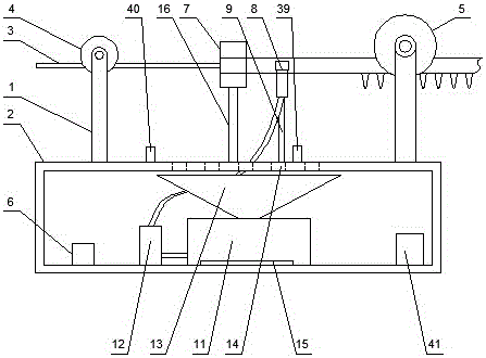
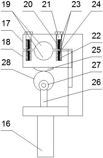
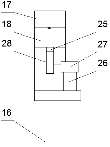
[0032] Such as Figures 1 to 5 As shown, a power transmission cable ice and snow removal device includes a running mechanism and a frame 2 connected below the running mechanism through a mechanical arm 1. The rear traveling wheel 4 and the front traveling wheel 5 stuck on the ice-coated unremoved part on the transmission line 3, a deicing mechanism is arranged on the frame 2, and the deicing mechanism is located between the rear traveling wheel 4 and the described Between the front traveling wheels 5, a wireless controller 6 is arranged on the left side inside the frame 2, and the traveling mechanism is electrically connected to the wireless controller 6; Module 7 and water knife segmentation module 8; Said water knife segmentation module 8 comprises the water knife support 9 that is arranged on the said frame 2, two jet cutting heads 10 that are arranged on the described water knife support 9, are arranged on The water tank 11 inside the frame 2 and the high-pressure pump 12...
Embodiment 2
[0039] Such as Image 6 , Figure 7 with Figure 8 As shown, the difference between it and Embodiment 1 is that an ice hanging removal module is set on the frame 2, and the ice hanging removal module is located between the water knife segmentation module 8 and the front road wheel 5, so The ice hanging removal module includes a removal module support 29 arranged on the frame 2 , a removal motor 30 arranged on the upper part of the removal module support 29 and a removal member arranged on the output shaft of the removal motor 30 .
[0040] Described clearing part comprises the rod body 31 that is arranged on the output shaft of described removal motor 30, and blind hole 32 is set on the both ends of described rod body 31, and end cover 33 is threadedly connected with described rod body 31 two ends, on described end cover 33 A through hole 34 is provided at a position corresponding to the position of the blind hole 32 , a block 35 is slidably arranged in the blind hole 32 , a...
Embodiment 3
[0044] Such as Figure 9 As shown, the difference between it and Embodiment 2 is that: the center of gravity adjustment module is provided at the bottom of the frame 2, and the center of gravity adjustment module includes a counterweight 42 that is slidingly arranged at the bottom of the frame 2 using a dovetail structure and is arranged on the bottom of the frame 2. The automatic telescopic rod 43 on the left side of the bottom of the frame 2, the free end of the automatic telescopic rod 43 is connected with the counterweight 42, and the automatic telescopic rod 43 is connected with the wireless controller 6 by electrical signals.
[0045] The automatic telescopic rod 43 is an electric telescopic rod.
[0046] In this embodiment, a center-of-gravity adjustment module is provided at the bottom of the frame to adjust the center of gravity of the device, so as to avoid the instability of the center of gravity from affecting the work of the device; The position of the block can ...
PUM
 Abstract
Description
Claims
Application Information
 - R&D
- Intellectual Property
- Life Sciences
- Materials
- Tech Scout
- Unparalleled Data Quality
- Higher Quality Content
- 60% Fewer Hallucinations
Browse by: Latest US Patents, China's latest patents, Technical Efficacy Thesaurus, Application Domain, Technology Topic, Popular Technical Reports.
© 2025 PatSnap. All rights reserved.Legal|Privacy policy|Modern Slavery Act Transparency Statement|Sitemap|About US| Contact US: help@patsnap.com


