Electrolyte injection device of storage battery

A filling device and battery technology, which is applied to battery pack parts, circuits, electrical components, etc., can solve the problems of slow filling speed, easy to pour out of the surface of the battery, and many impurities, and achieve the effect of fast filling speed.

Active Publication Date: 2017-05-10
烟台金潮宇科蓄电池有限公司
View PDF5 Cites 1 Cited by
  • Summary
  • Abstract
  • Description
  • Claims
  • Application Information

AI Technical Summary

Problems solved by technology

[0006] In order to overcome the problems of the present battery electrolyte filling method, when pouring in non-standard containers, direct pouring will contain more impurities, the filling speed is too slow, and it is easy to pour out of the surface of the battery, overflow or be dissatisfied when filling. The technical problem to be solved by the present invention is to provide a kind of battery electrolysis that uses a professional container to fill without too many impurities, the filling speed is fast, and it is not easy to pour out the surface of the battery when filling, and it will not overflow or be dissatisfied. liquid filling device

Method used


Image

  • Electrolyte injection device of storage battery
  • Electrolyte injection device of storage battery
  • Electrolyte injection device of storage battery

Examples


Embodiment 1

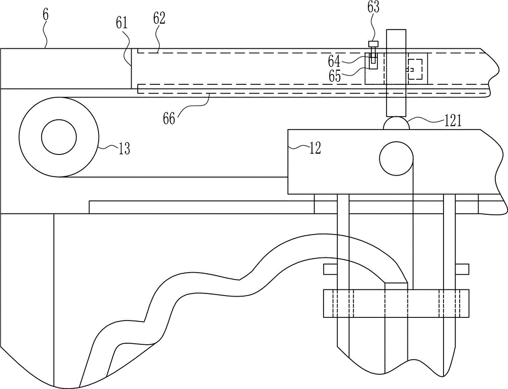
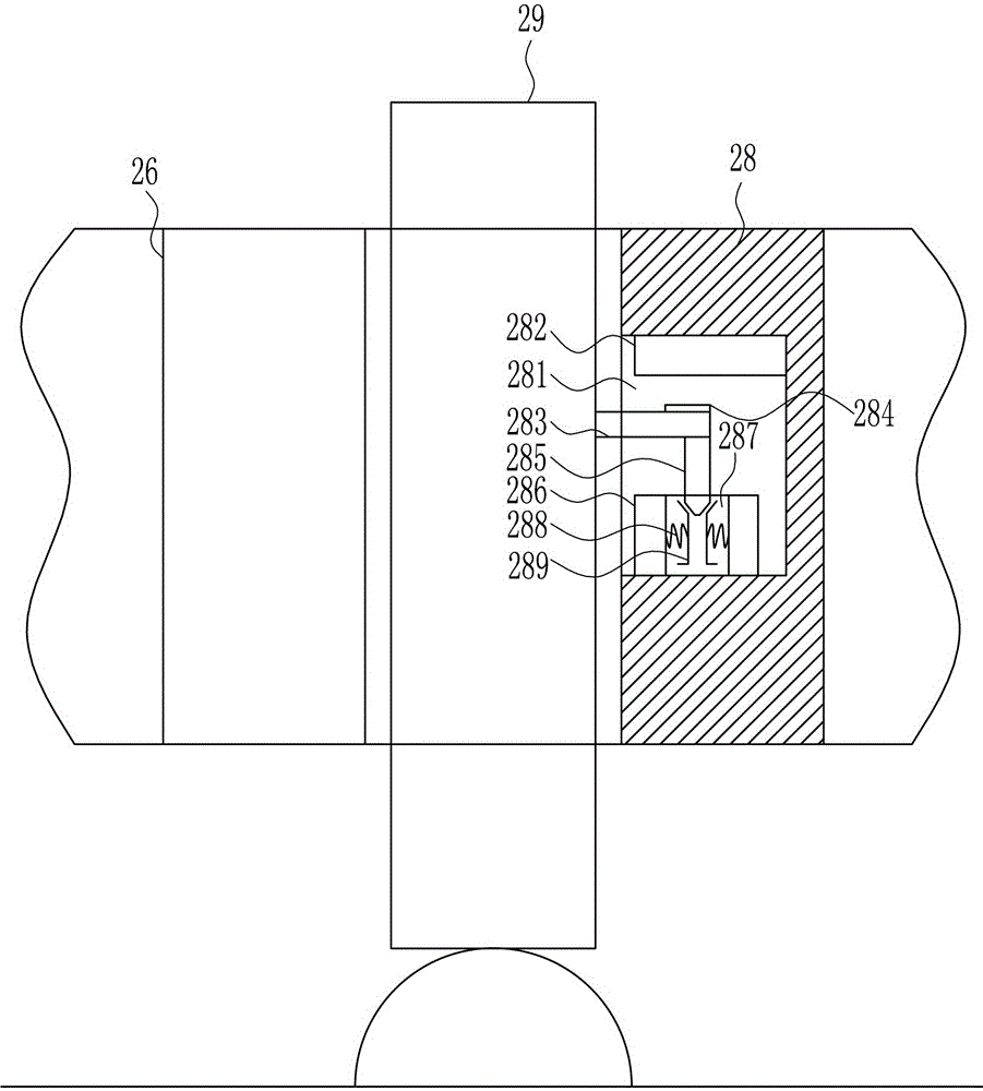
[0027] A battery electrolyte filling device, such as Figure 1-4 As shown, it includes bottom plate 1, left plate 3, right plate 4, top box 5, top plate 6, electrolyte tank 7, water pump 8, hose 9, first track 10, first slider 11, movable block 12, The first block 121, the rotating shaft 13, the driving wheel 14, the transmission wheel 15, the conveyor belt 16, the electric reel 17, the pull wire 18, the slide bar 19, the sliding sleeve 20, the first through hole 21, the filling pipe 22, the first A travel switch 23, a second travel switch 24, a third travel switch 25, a gear block 26, a contact block 29, a storage battery 30, a filler port 31 and a gear device 28, the middle part of the upper end of the base plate 1 is provided with a battery slot 2, and the base plate The left side plate 3 is installed on the left side of the upper end of 1 by welding, the right plate 4 is installed on the right side of the upper end of the bottom plate 1 by welding, and the electrolyte tank...


PUM


Abstract

The invention relates to a storage battery, in particular to an electrolyte injection device of a storage battery, and aims at achieving the technical effect of providing the electrolyte injection device of the storage battery, which does not cause excessive impurities by adopting a professional container and is relatively high in injection speed, and of which an electrolyte is not easily poured out of the surface of the storage battery, does not overflow or is not fully poured during injection. In order to solve the technical problems, the electrolyte injection device of the storage battery comprises a bottom plate, a left plate, a right plate, a top box, a top plate, an electrolyte tank, a water pump, a hose, a first track, a first sliding block, a movable block, a first baffle plate, a rotating shaft and the like, wherein a battery jar is formed in the middle of the upper end of the bottom plate; the left plate is arranged at the left side of the upper end of the bottom plate in a welding manner; and the right plate is arranged at the right side of the upper end of the bottom plate in a welding manner. The effects that the excessive impurities are not generated by adopting the professional container, the injection speed is relatively high, and the electrolyte is not easily poured out of the surface of the storage battery, does not overflow or is not fully poured during injection are achieved.

Description

technical field [0001] The invention relates to a battery, in particular to a battery electrolyte filling device. Background technique [0002] Battery A battery is a device that directly converts chemical energy into electrical energy. It is a rechargeable battery designed to recharge through a reversible chemical reaction. It usually refers to a lead-acid battery. It is a type of battery and belongs to the secondary battery. secondary battery. Its working principle: When charging, the external electric energy is used to regenerate the internal active material, and the electric energy is stored as chemical energy. When it needs to be discharged, the chemical energy is converted into electric energy output again, such as the mobile phone battery commonly used in life. [0003] An electrolytic capacitor using electrolyte as the cathode, when the dielectric is broken down, as long as the breakdown current does not continue, the capacitor can self-heal. But electrolyte also h...

Claims


Application Information

Patent Timeline
IPC IPC(8): H01M2/36
CPCH01M50/60H01M50/668Y02E60/10
Inventor 不公告发明人
Owner 烟台金潮宇科蓄电池有限公司
Why Eureka
Try Eureka