Intensive tempered glass surface stress gauge
A technology of tempered glass and surface stress, applied in the field of optical detection, can solve the problems of large size of lifting mechanism, complex structure, limited flexible application of stress meter, etc., to achieve the effect of improving operability, reducing the size of the whole machine, and simplifying the overall structure
- Summary
- Abstract
- Description
- Claims
- Application Information
AI Technical Summary
Problems solved by technology
Method used
Image
Examples
Embodiment 1
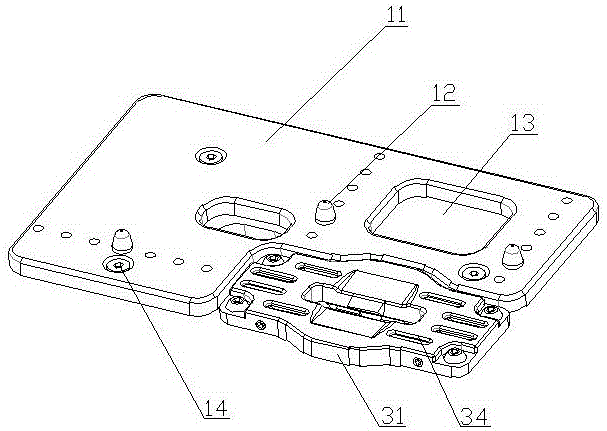
[0026] figure 1 A structural schematic diagram of an embodiment of the intensive tempered glass surface stress meter of the present invention is shown, which is also a schematic diagram of a preferred embodiment. Such as figure 1 As shown, the strain gauge described in this embodiment includes a worktable 10, an illumination unit 20, a light refraction unit 30, an imaging unit 40, and an image processing unit (not shown in the figure), and the illumination unit 20 and the imaging unit The unit 40 is located under the worktable 10, the light refraction unit 30 is located on the worktable for placing samples to be inspected, the illumination unit, the light refraction unit and the imaging unit form an optical path, The light refraction unit is located in the light emitting direction of the illumination unit, the imaging unit is located at the rear end of the optical path, the light emitted by the illumination unit is incident on the sample to be inspected on the light refractio...
Embodiment 2
[0033] figure 2 Another structure of the strain gauge of the present invention is shown, as figure 2 As shown, an intensive tempered glass surface stress instrument includes a workbench 10, an illumination unit 20, a light refraction unit 30, an imaging unit 40, and an image processing unit (not shown in the figure), and the illumination unit and the The imaging unit is located under the worktable, and the light refraction unit is located on the worktable for placing samples to be inspected. The illumination unit, the light refraction unit and the imaging unit form an optical path. The light refraction unit is located in the light emitting direction of the illumination unit, and the imaging unit is located at the rear end of the optical path. The light emitted by the illumination unit is incident on the sample to be inspected on the light refraction unit, and enters the sample after total reflection. The imaging unit is used for imaging, the imaging unit is connected to the...
PUM
 Abstract
Description
Claims
Application Information
 - R&D Engineer
- R&D Manager
- IP Professional
- Industry Leading Data Capabilities
- Powerful AI technology
- Patent DNA Extraction
Browse by: Latest US Patents, China's latest patents, Technical Efficacy Thesaurus, Application Domain, Technology Topic, Popular Technical Reports.
© 2024 PatSnap. All rights reserved.Legal|Privacy policy|Modern Slavery Act Transparency Statement|Sitemap|About US| Contact US: help@patsnap.com


