
Belt pulley

A pulley and ring technology, applied in belts/chains/gears, components with teeth, portable lifting devices, etc., can solve the problems of long production cycle, poor dimensional accuracy of pulley parts, and poor product quality, and save production. cost, improved labor conditions, and the effect of reducing equipment investment

Inactive Publication Date: 2017-05-10
山东时风(集团)有限责任公司
View PDF5 Cites 2 Cited by
  • Summary
  • Abstract
  • Description
  • Claims
  • Application Information

AI Technical Summary

Problems solved by technology

[0002] In the current industrial production, all kinds of pulley parts are widely used, but due to the inherent characteristics of the pulley parts, they are all shaped towards the mold sand ground, which makes the dimensional accuracy of the pulley parts inconsistent and inconsistent, which causes parts high scrap rate
At present, the production of pulley parts is all obtained through mechanical processing methods, that is to say, the method of cutting the blank of the part is used to process it into the required pulley, which generally requires high processing accuracy and long production cycle. The production rate of the product is high, so that the production efficiency of the grooved part is low, and the quality of the product is poor; as for the direct casting of the mold of the part, although there are some similar methods, they are limited to experiments, and there is no real casting method. High-precision mold process methods, such as some companies using high-precision ceramic casting, although they can also cast pulleys, but compared with this process, the cost is too high, and it is not convenient for mechanized production. The mold cannot maintain continuous high-precision production. To sum up, it is urgent to design a new processing method for pulley parts to meet the needs of modern production.

Method used


Image

  • Belt pulley
  • Belt pulley
  • Belt pulley

Examples


Embodiment 1

[0028] The process steps of direct casting groove shape of rear axle clutch pulley of three-wheeled automobile are as follows:

[0029] (1) According to the groove shape requirements of the rear axle clutch pulley of the three-wheeled automobile, at first make a shell shape completely consistent with its groove shape as a master mold;

[0030] (2) Make the outer shape of the shell mold. The outer shape of the shell mold is required to be matched with the core shooter of coated sand. The outer dimension of the shell mold is required to be the maximum size of the master mold plus 8mm. When mating, its wall thickness is guaranteed to be 8mm;

[0031] (3) Fix the master mold on the workbench of the sand shooting machine, and close the iron mold shape, heat it to 260°C and keep it warm for 30 minutes to shoot the sand;

[0032] (4) Shoot the coated sand onto the pre-designed iron mold through the sand shooting hole of the sand shooting machine, so that the coated sand fills the ca...

Embodiment 2

[0037] The process steps of direct casting groove shape of rear axle clutch pulley of three-wheeled agricultural vehicles are as follows:

[0038] (1) According to the groove shape requirements of the three-wheel agricultural steam rear axle clutch pulley, firstly make a model that is completely consistent with its groove shape as the master mold;

[0039] (2) Make the outer shape of the shell mold. The shape of the shell mold is required to be matched with the core shooter of the coated sand. The inner size of the cavity is required to be the maximum size of the master mold plus 8mm, so that the inner cavity of the outer shape of the shell mold is matched with the groove-shaped master mold model. When the wall thickness is guaranteed to be 8mm;

[0040] (3) Fix the master mold on the workbench of the sand shooting machine, and close the shape of the hot core box, heat it to 260°C and keep it warm for 30 minutes to shoot the sand;

[0041] (4) Shoot the coated sand into the p...

Embodiment 3

[0046] The process steps of direct casting groove shape of rear axle clutch pulley of three-wheeled agricultural vehicles are as follows:

[0047] (1) According to the groove shape requirements of the rear axle clutch pulley of the three-wheeled agricultural vehicle, first make a model that is completely consistent with its groove shape as a master mold;

[0048] (2) Make the outer shape of the shell mold. The shape of the shell mold is required to be matched with the core shooter of the coated sand. The inner size of the cavity is required to be the maximum size of the master mold plus 8mm, so that the inner cavity of the outer shape of the shell mold is matched with the groove-shaped master mold model. When the wall thickness is guaranteed to be 8mm;

[0049] (3) Fix the master mold on the workbench of the sand shooting machine, and close the shape of the hot core box, heat it to 280°C and keep it warm for 30 minutes to shoot the sand;

[0050] (4) Shoot the coated sand int...


PUM


Abstract

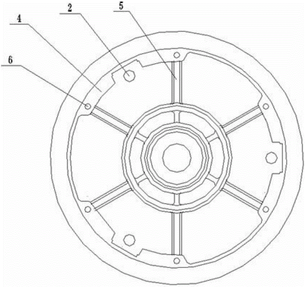
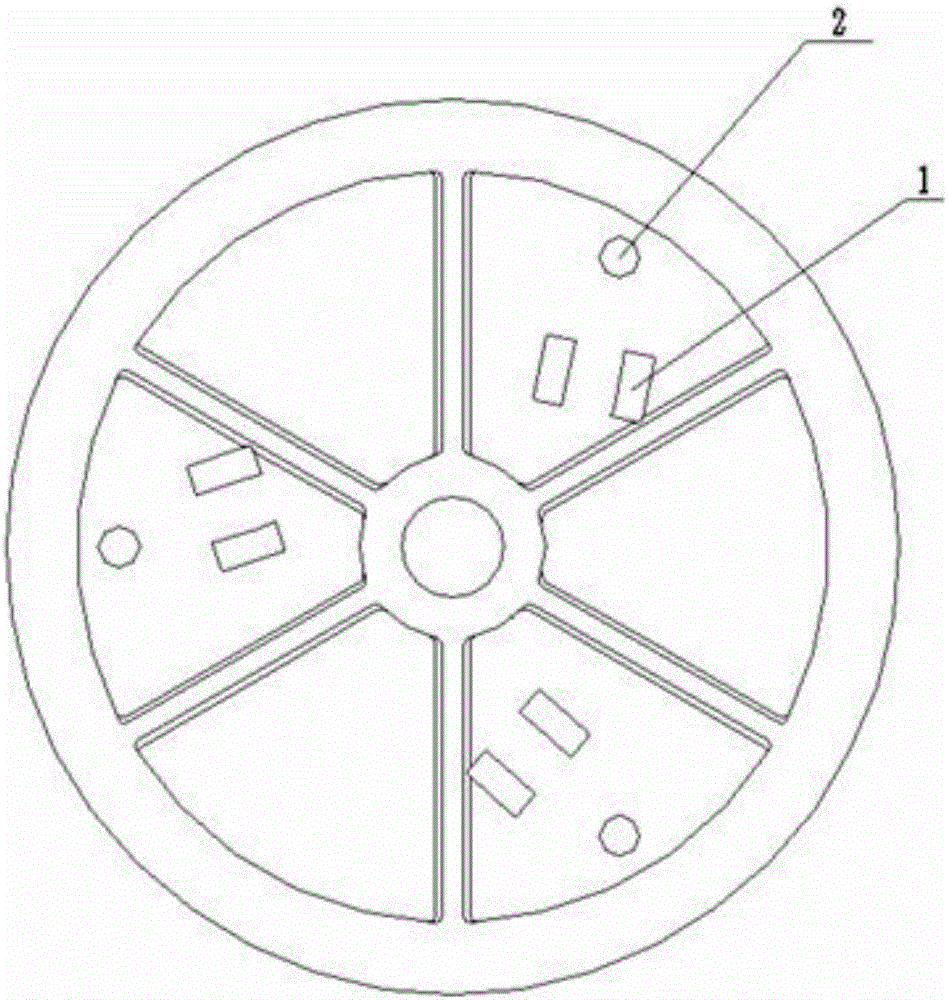
The invention provides a belt pulley. The belt pulley is in the basic shape of a circular ring, a flexible movable block with an annular opening is arranged on the outer diameter of the circular ring, a clutch supporting surface is arranged at one side of the circular ring, a bearing hole is formed in the middle of the clutch supporting surface, fan-shaped grooves are formed in the outer wall of the clutch supporting surface, and convex lugs are arranged in grooves which are arranged at intervals; a pressing disc limiting groove is formed in the inner wall of the circular ring of the inner side of the clutch supporting surface, grooves are formed in the middles of convex portions of the pressing disc limiting groove, installation holes are formed in the two sides of each convex portion, lever separation holes are formed in the portions, corresponding to the grooves, of the clutch supporting surface, and clutch plate installation platforms are arranged at the positions, corresponding to the installation holes, of the inner diameter of the pressing disc limiting groove. According to the belt pulley, a direct casting shaping process method is adopted, a complete groove-shaped cavity is obtained by adopting a precoated sand shell molding process, a groove shape is directly cast, a process method which is free of cutting or needs an extremely little amount of cutting is obtained, and method is low in cost, simple, easy to operate and suitable for being used by most enterprises.

Description

technical field [0001] The invention relates to a belt pulley, in particular to a method for directly casting and modeling the belt pulley parts. Background technique [0002] In the current industrial production, all kinds of pulley parts are widely used, but due to the inherent characteristics of the pulley parts, they are all shaped towards the mold sand ground, which makes the dimensional accuracy of the pulley parts inconsistent and inconsistent, which causes parts High scrap rate. At present, the production of pulley parts is all obtained through mechanical processing methods, that is to say, the method of cutting the blank of the part is used to process it into the required pulley, which generally requires high processing accuracy and long production cycle. The production rate of the product is high, so that the production efficiency of the grooved part is low, and the quality of the product is poor; as for the direct casting of the mold of the part, although there a...

Claims


Application Information

Patent Timeline
Patent Type & Authority Applications(China)
IPC IPC(8): F16H55/36B22C9/28B22C15/24
CPCF16H55/36B22C9/28B22C15/24
Inventor 刘成强于子岭纪昌勇徐海港李汝学许爱国张中凯刘兴明
Owner 山东时风(集团)有限责任公司
Learn More