Axial current force curtain sail current wheel

A technology of flow curtain and sail flow wheel, which is applied to wind turbines, wind turbines, wind turbine control and other directions that are consistent with the wind direction, can solve the problem that the three-blade wind wheel has less flow area and weak flow power, increases transportation costs and Installation costs, high mold costs, etc., to achieve the effect of improving the use value, reducing selectivity, and eliminating mold production

Pending Publication Date: 2017-05-10
毛永波
View PDF0 Cites 5 Cited by
  • Summary
  • Abstract
  • Description
  • Claims
  • Application Information

AI Technical Summary

Problems solved by technology

[0004] The existing wind wheel or water wheel blades are all fixed on the hub by a hard plate or hard propeller. This tough physique has extraordinary performance but has more shortcomings. Although this common wind wheel adopts a light The high-quality fiber material has greatly improved the weight problem, but its weight is still heavy compared to the weak flow power, and the scraping area of ​​the existing three-blade wind wheel is too small for weak flow power, it must be molded and the cost of the mold is very expensive , the production cycle is long, and its length directly increases its transportation cost and installation cost. When it is designed, in order to deal with strong winds, its wind area and blade strength must be accurately calculated, planned and tested. What is more difficult is normal temperature and normal sunny weather. How to get motivated on long days? So the existing wind wheel has a fairly high choice for the environment
[0005] The diameter of the Ferris wheel in the amusement park is quite large and must be driven by electricity, which directly increases the operating cost

Method used


Image

  • Axial current force curtain sail current wheel
  • Axial current force curtain sail current wheel
  • Axial current force curtain sail current wheel

Examples


Embodiment Construction

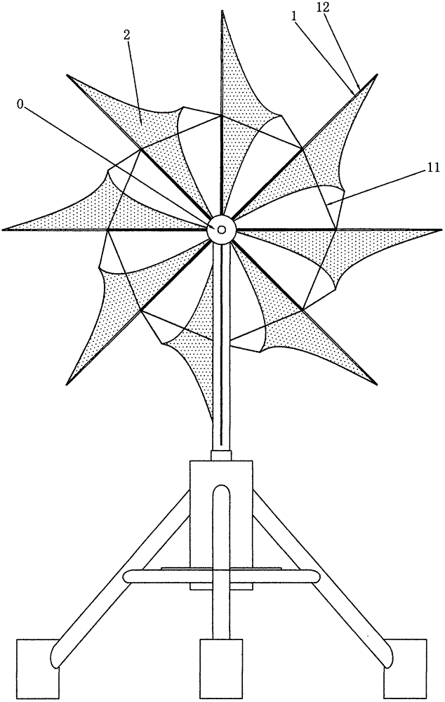
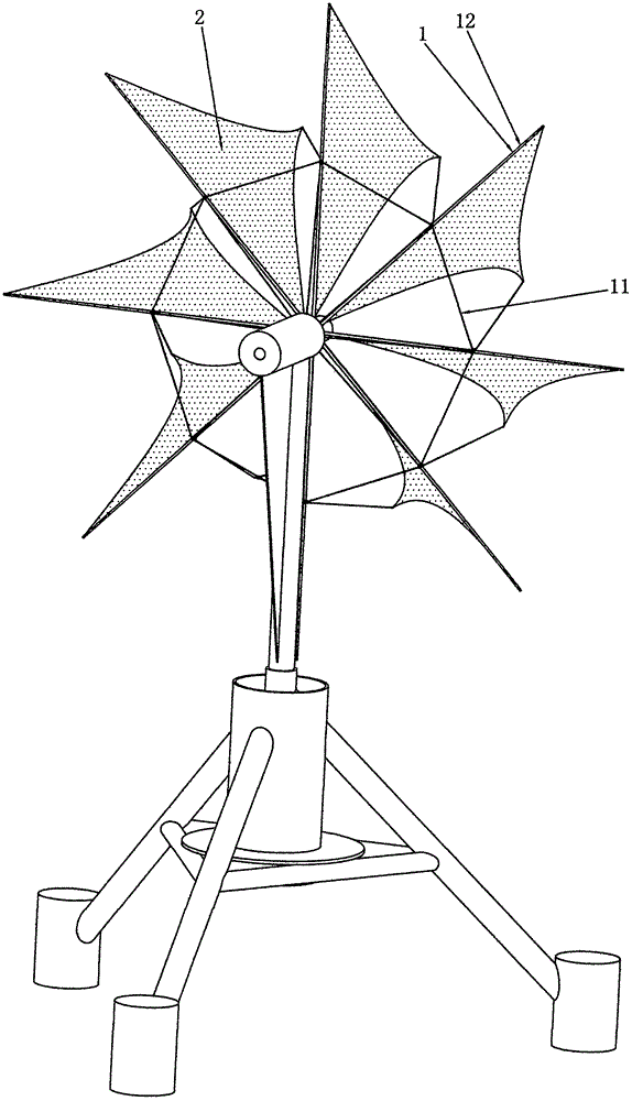
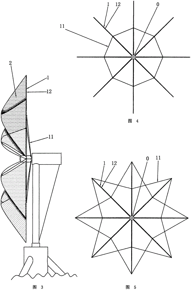
[0058] Axial flow curtain sail wheel, as shown in Figure 17, 19, 20, 21, 22, 32, it includes: flow wheel frame 1, curtain sail 2; described flow wheel frame 1 is composed of outer wheel 10, wheel hub 0 , a chain cable 11 or a strut 12; the outer wheel 10 has at least one outer ring or an outer circular tube body and an outer frame; the chain cable 11 is a chain or a rope; the chain cable 11 or a strut 12 surround the wheel hub 0 in an axial ring array and connect the two ends of each piece to tighten or tighten the hub 0 and the outer wheel 10 to be coaxial and concentric; 0 axial annular array; or the curtain sail 2 artificially swings or stretches on the wheel frame 1 and surrounds the hub 0 axial annular array.

[0059] Axial flow curtain sail wheel, such as figure 1 , 2, 4, 5, 6, 7, 9, 10, 29, 30, it includes: a wheel frame 1, a curtain sail 2; 11; the strut 12 is fixed on the hub 0 with one end and surrounds the hub 0 in an axial circular array; the chain cable 11 is a...


PUM


Abstract

The invention discloses an axial current force curtain sail current wheel. The axial current force curtain sail current wheel comprises a current wheel frame and curtain sails. The current wheel frame is made from stainless steel pipe body chain links or lightweight alloy pipe body chain links or rubber-plastic pipe body chain links or fiber medium pipe body chain links or fiber metal synthetic pipe body chain links or fiber strengthened plastic pipe body chain links or plastic metal synthetic pipe body chain links, fibers are carbon fibers or graphene carbon fibers, the current wheel frame is made from a lightweight raw material, and the fabric or non-woven fabric curtain sails are used as wind scraping blades, so that the lightweight current wheel is formed; reels or oscillating bars and pulley sets are used for automatically adapting to the current force environment so as to automatically and movably unwind, stretch, retract or rotatably swing the curtain sails, so that controllable variable current scraping is achieved, power is balanced by pressurizing slow current and depressurizing rapid current, meanwhile, strong current damage is coped, and weak current power is greatly improved; or paper curtain sails are used as the wind scraping blades, traditional fixed blade current wheels are replaced in a consumable mode, the weight and manufacturing cost of the current wheel are lowered, the slow current power is increased, the selectivity of a wind wheel to the environment is reduced, and wind power driving of sky wheels in fairgrounds is achieved.

Description

[0001] 【Technical field】 [0002] The invention relates to hydraulic wind power equipment, in particular to a hydraulic wind power flow wheel and a ferris wheel in an amusement park. [0003] 【Background technique】 [0004] The existing wind wheel or water wheel blades are all fixed on the hub by a hard plate or hard propeller. This tough physique has extraordinary performance but has more shortcomings. Although this common wind wheel adopts a light The high-quality fiber material has greatly improved the weight problem, but its weight is still heavy compared to the weak flow power, and the scraping area of ​​the existing three-blade wind wheel is too small for weak flow power, it must be molded and the cost of the mold is very expensive , the production cycle is long, and its length directly increases its transportation cost and installation cost. When it is designed, in order to deal with strong winds, its wind area and blade strength must be accurately calculated, planned an...

Claims


Application Information

Patent Timeline
IPC IPC(8): F03D1/06F03D7/04
CPCF03D1/0633F03D7/0236F03D7/042Y02E10/72Y02P70/50
Inventor 毛永波
Owner 毛永波
Why Eureka
Try Eureka