
Connecting device of electromagnetic stirrer coil and electronic control system driving power supply

An electromagnetic stirrer and driving power technology, which is applied in the field of metal material processing, can solve the problems of unsuitable storage, difficult disassembly and assembly, low system safety, etc., to prevent contact with hot and humid environment, facilitate maintenance, replacement and disassembly, and improve safety. Effect

Active Publication Date: 2017-05-10
有研金属复材技术有限公司
View PDF7 Cites 2 Cited by
  • Summary
  • Abstract
  • Description
  • Claims
  • Application Information

AI Technical Summary

Problems solved by technology

The electromagnetic stirring coil is mostly placed inside or outside the continuous casting water tank, while the electromagnetic stirring electric control system is equipped with a separate power distribution cabinet and operation control panel. The electromagnetic stirring coil and the driving part of the electromagnetic stirring electric control system are connected by cables. The ambient temperature of the casting site is relatively high, and the water vapor is relatively large. The connection between the electromagnetic stirring coil and the electromagnetic stirring electric control system must be safe and reliable to prevent dangers such as leakage. Disassemble and replace the cables at the driving end of the electromagnetic stirring electric control system, and the replaced electromagnetic stirrers often carry very long cables, which makes it not suitable for storage
[0003] It can be seen from the above that the connection between the electromagnetic stirrer coil and the drive power supply of the electronic control system in the prior art is not easy to disassemble, and it is easily affected by high temperature and high tide environment, resulting in low system safety

Method used


Image

  • Connecting device of electromagnetic stirrer coil and electronic control system driving power supply
  • Connecting device of electromagnetic stirrer coil and electronic control system driving power supply

Examples


Embodiment Construction

[0015] The embodiments will be described in detail below in conjunction with the accompanying drawings.

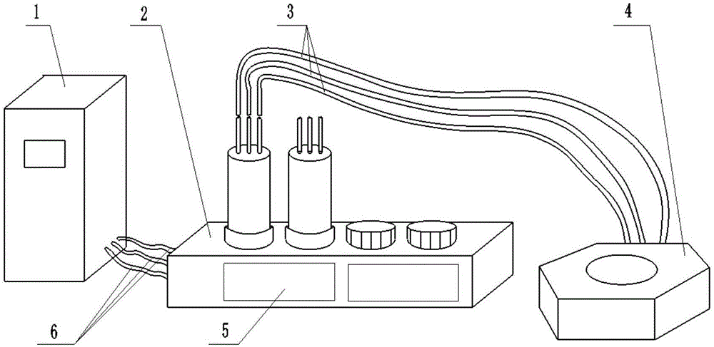
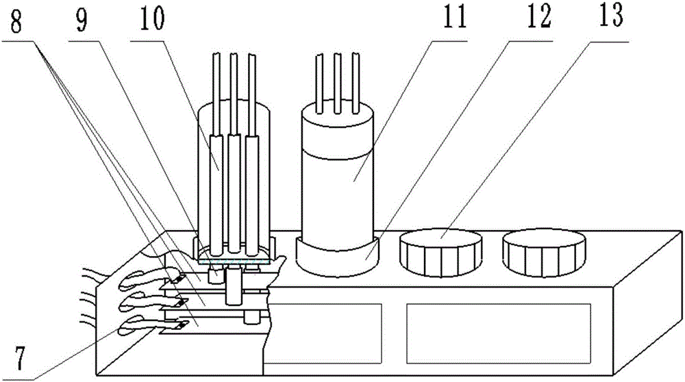
[0016] Such as figure 1 The schematic diagram of the connection between the metal continuous casting electromagnetic stirrer coil and the drive power supply of the electric control system is shown, which includes the drive power supply 1 of the electromagnetic stirrer electric control system, the intermediate junction box 2, the electromagnetic stirrer coil 4, and the drive cable 3 of the electromagnetic stirrer coil , Electromagnetic stirring electric control system drive power supply output cable 6 and other devices. The driving power supply 1 of the electromagnetic stirring electric control system is connected to the intermediate junction box 2 through the driving power output cable 6 of the electromagnetic stirring electric control system, and the intermediate junction box 2 is connected to the electromagnetic stirrer coil 4 through the driving cable 3 of the electroma...


PUM


Abstract

The invention belongs to the field of processing of metal materials and particularly relates to a connecting device of an electromagnetic stirrer coil and an electronic control system driving power supply. The connecting device comprises a driving power supply output cable, an intermediate junction box and an electromagnetic stirrer coil driving cable; the electronic control system driving power supply is connected to the intermediate junction box by the driving power supply output cable; and the intermediate junction box is connected to the electromagnetic stirrer coil through the electromagnetic stirrer coil driving cable. The connecting device provided by the invention facilitates the replacement of toolings such as a crystallizer, a water tank and the stirrer coil; and the connecting ends of driving cables of different stirrers which can apply the electronic control system driving power supply of the same electromagnetic stirrer are integrated on one intermediate junction box, so that the condition that the connecting ends make contact with the humid and warm environment is avoided, and the safety of the system is improved.

Description

technical field [0001] The invention belongs to the field of metal material processing, and in particular relates to a connection device between a coil of an electromagnetic stirrer and a driving power supply of an electric control system. Background technique [0002] In the prior art, the crystallization electromagnetic stirring system for metal continuous casting mainly includes two parts: the electromagnetic stirring coil and the electromagnetic stirring electric control system. It provides power for the electromagnetic stirrer and a user-friendly operation interface to control various parameters of the stirring process. The electromagnetic stirring coil is mostly placed inside or outside the continuous casting water tank, while the electromagnetic stirring electric control system is equipped with a separate power distribution cabinet and operation control panel. The electromagnetic stirring coil and the driving part of the electromagnetic stirring electric control syste...

Claims


Application Information

Patent Timeline
Patent Type & Authority Applications(China)
IPC IPC(8): B22D11/115B22D11/16
CPCB22D11/115B22D11/166
Inventor 杨玉洁张志峰刘建朝高明伟李豹陈春生王亚宝
Owner 有研金属复材技术有限公司
Learn More