A gas dry purification cyclone adsorption coupling equipment
A technology of dry purification and coupling equipment, which is applied in separation methods, chemical instruments and methods, and separation of dispersed particles. It can solve the problems of high-temperature gas loss of effective energy, large footprint, and easy deterioration of solvents, and achieves no rotating parts. , simple structure and long operation period
- Summary
- Abstract
- Description
- Claims
- Application Information
AI Technical Summary
Problems solved by technology
Method used
Image

Examples
Embodiment 1
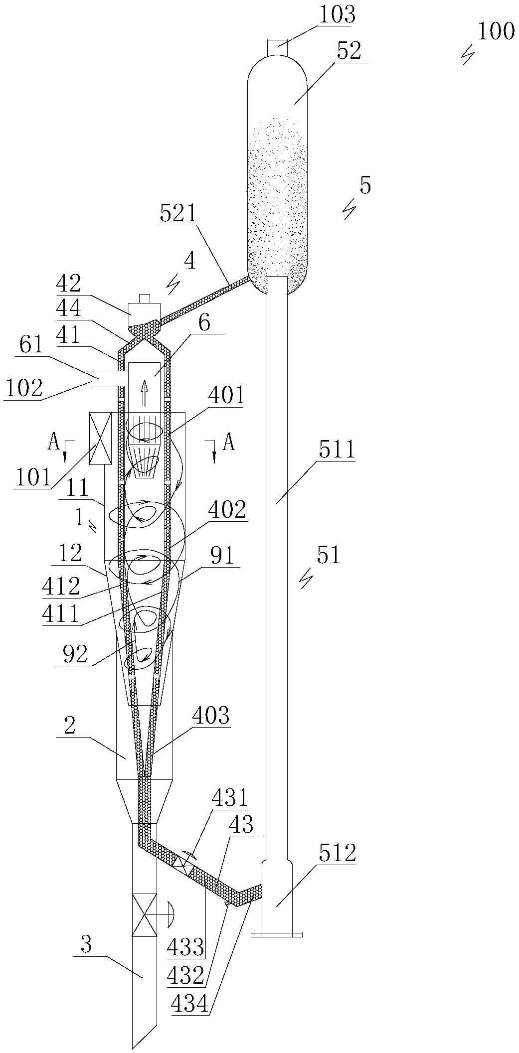
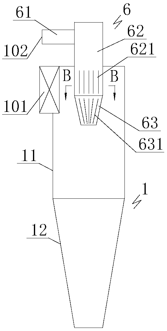
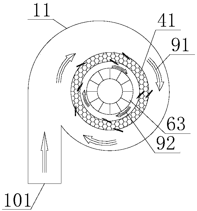
[0084] Such as Figure 1a to Figure 1e As shown, the gas dry purification cyclone adsorption coupling device 100 is a sandwich type cyclone adsorption coupling device, the adsorbent moving bed 4 includes a particle moving interlayer structure 41 coaxially arranged with the cyclone separator 1 and containing adsorbent particles, The top of the cyclone separator 1 is pierced with a central exhaust pipe 6, the particle moving interlayer structure 41 is passed through the cyclone separator 1 from top to bottom, and the inner cavity of the particle moving interlayer structure 41 is sleeved with a central exhaust pipe 6, and the particle moving interlayer structure 41 is sleeved with a central exhaust pipe 6. The bottom of the moving interlayer structure 41 is located in the ash hopper 2; the particle moving interlayer structure 41 corresponds to the position of the gas inlet 101 to be separated to form an inlet rectification area 401, and the particle moving sandwich structure 41 co...
Embodiment 2
[0095] Such as Figure 2a , Figure 2b As shown, the gas dry purification cyclone adsorption coupling device 100 is a column-cone cyclone adsorption coupling device, and the adsorbent moving bed 4 includes a particle-moving column-cone structure coaxially arranged with the cyclone separator 1 and containing adsorbent particles. 45. The inside of the particle moving cylindrical cone structure 45 and above the gas inlet 101 to be separated is provided with a central exhaust cavity 450. The particle moving cylindrical cone structure 45 penetrates into the cyclone separator 1 from top to bottom, and the particles move The bottom of the cylindrical cone structure 45 is located in the ash hopper 2; the position of the particle moving cylindrical cone structure 45 corresponding to the gas inlet 101 to be separated constitutes an inlet rectification area 401, and the particle moving cylindrical cone structure 45 corresponds to the cyclone separator 1 and is located below the gas inlet...
Embodiment 3
[0108] Such as Figure 3a to Figure 3d As shown, the gas dry purification cyclone adsorption coupling device 100 is an external cyclone adsorption coupling device; the top of the cyclone separator 1 is provided with a central exhaust pipe 6 from the outside to the inside, and the adsorbent moving bed 4 includes a cyclone separator. 1 The particle moving external interlayer structure 46 arranged coaxially with the cyclone separator 1 above the outside and containing the adsorbent particles, and the upper part of the central exhaust pipe 6 is sealed and sleeved on the particle moving external interlayer structure 46 from bottom to top In the inner cavity of the particle moving external sandwich structure 46, the outer side of the particle moving external sandwich structure 46 is coaxially spaced, which can communicate with the internal cavity of the particle moving external sandwich structure 46, and an exhaust pipe structure 64 with a top and bottom seal, the exhaust pipe A hor...
PUM
| Property | Measurement | Unit |
|---|---|---|
| particle diameter | aaaaa | aaaaa |
Abstract
Description
Claims
Application Information
 - R&D
- Intellectual Property
- Life Sciences
- Materials
- Tech Scout
- Unparalleled Data Quality
- Higher Quality Content
- 60% Fewer Hallucinations
Browse by: Latest US Patents, China's latest patents, Technical Efficacy Thesaurus, Application Domain, Technology Topic, Popular Technical Reports.
© 2025 PatSnap. All rights reserved.Legal|Privacy policy|Modern Slavery Act Transparency Statement|Sitemap|About US| Contact US: help@patsnap.com