Lifting net cage
A lift-type, net-cage technology, applied in the direction of valve devices, climate change adaptation, engine components, etc., can solve problems such as typhoon damage, achieve low cost, facilitate the installation of floating pipes, and prevent fish from being stolen
- Summary
- Abstract
- Description
- Claims
- Application Information
AI Technical Summary
Problems solved by technology
Method used
Image

Examples
Embodiment 1
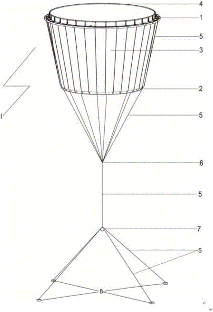
[0052] Embodiment 1: see Figure 1-Figure 4 , a lifting type net cage, the lifting type net cage includes: at least one floating tube 1 as the floating body of the lifting type net cage, 3 floating tubes are provided in this embodiment, namely the middle floating tube, the inner floating tube and the outer side Floating tubes, three floating tubes are arranged in parallel to surround a circular breeding space. According to the needs, it can also be set as two floating tubes, one floating tube or even multiple floating tubes, and can also be surrounded by triangle, square or octagonal breeding. space.
[0053] There are multiple floating pipe connectors on the floating pipe, in order to fix the floating pipe into one;
[0054] A plurality of handrail frames 4 are placed on the top of the floating pipe connector and placed inwardly;
[0055] at least one handrail tube mounted on the handrail frame, bent into a circle;
[0056] At least one set of net 3 is installed on the han...
Embodiment 2
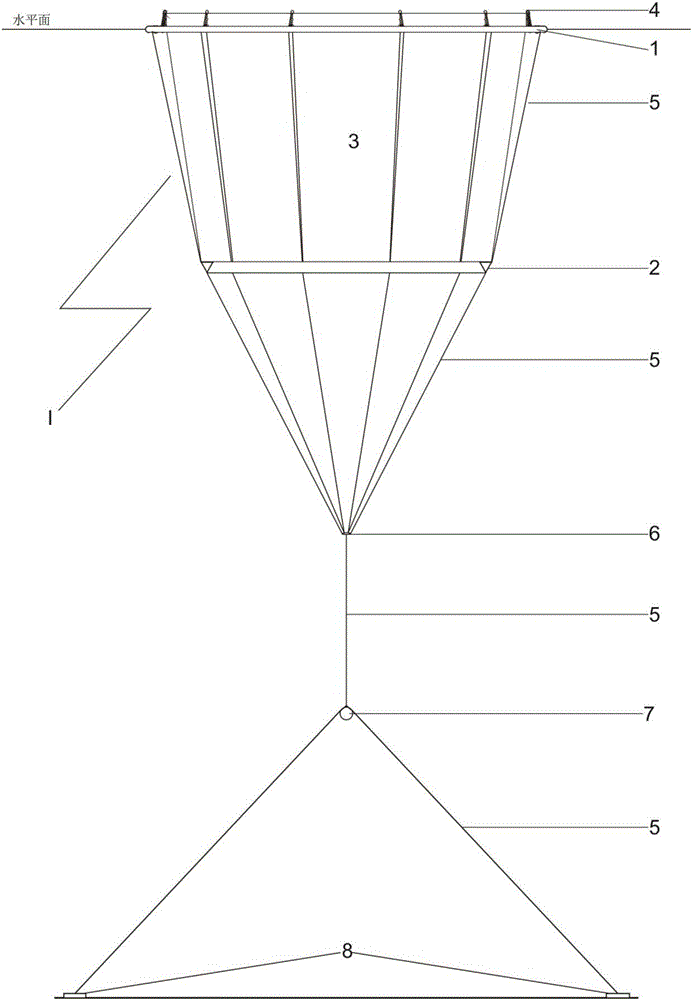
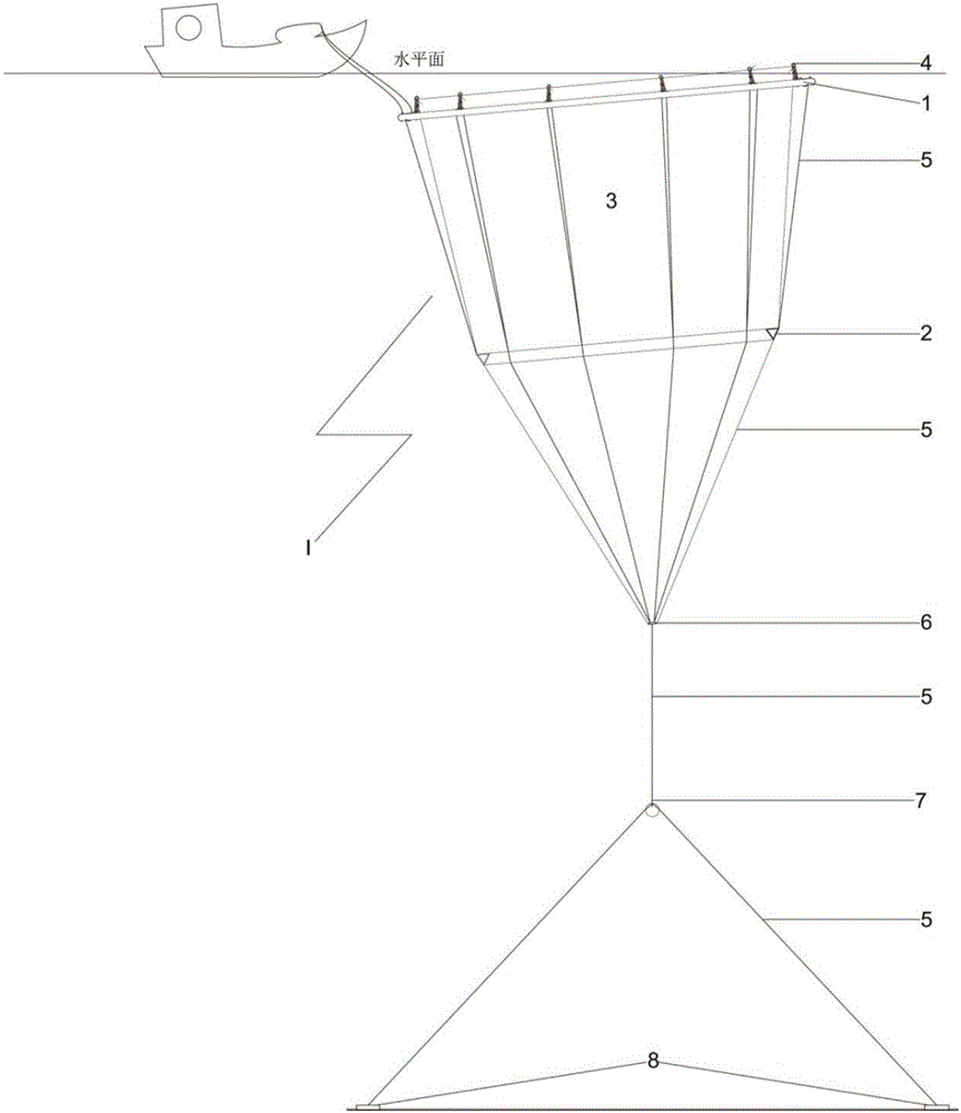
[0073] Example 2: see Figure 11 , the hub in this technical solution is set as a cylindrical hub 6, the top and bottom of the cylindrical structure are provided with valves, when initially set, the buoyancy of the sinker 7 is greater than the buoyancy of the hub, and the hub set as this structure can be faster Realize the rise and fall of the net cage. The floating pipe in this technical solution is provided with one, two or three. When it is set to one, the rise and fall of the entire net cage is controlled by the valve on the hub. When three floating pipes are used, the hub and the valves on the floating pipes can be adjusted simultaneously, the rising and falling speed of the whole net cage is faster, and the adjustment is more convenient. All the other structures and advantages are exactly the same as those in Embodiment 1.
[0074] The main design principles of this technical solution are as follows:
[0075] When floating, the buoyancy of (outer tube + middle tube + in...
Embodiment 3
[0080] Embodiment 3: see Figure 7 , the valve includes a control valve, a spool and a valve base 1.2, wherein the spool includes a spool body and a spool base 7.2 arranged at the bottom of the spool body, the spool body is provided with a spool thread 7.1, and the upper end is set There is a spool port 7.3, and the valve is formed by wrapping the spool base with liquid plastic. The spool port is used for air in and out, and water in and out. There are threads on each spool to install the valve control valve and control the opening and closing of the valve. The bottom of the spool is the spool base. When the liquid plastic passes through the valve When the mold is poured, it can be connected into a whole, and it will be very firm after cooling. Figure 8A It is the plan view of the valve mold. From the picture, we can see that the valve mold is composed of upper and lower parts. The middle part is a circle, which can put the floating tube in. In the upper part of the valve mo...
PUM
 Abstract
Description
Claims
Application Information
 - R&D
- Intellectual Property
- Life Sciences
- Materials
- Tech Scout
- Unparalleled Data Quality
- Higher Quality Content
- 60% Fewer Hallucinations
Browse by: Latest US Patents, China's latest patents, Technical Efficacy Thesaurus, Application Domain, Technology Topic, Popular Technical Reports.
© 2025 PatSnap. All rights reserved.Legal|Privacy policy|Modern Slavery Act Transparency Statement|Sitemap|About US| Contact US: help@patsnap.com