
A front collimator for ct

A pre-collimator and collimator technology, applied in the field of particle or ionizing radiation processing, can solve the problems of increasing the collimation slit width, image quality degradation, image artifacts, etc., to achieve uniform width and work efficiency. High and low cost effect

Active Publication Date: 2018-12-25
四川明峰医疗科技有限公司
View PDF6 Cites 0 Cited by
  • Summary
  • Abstract
  • Description
  • Claims
  • Application Information

AI Technical Summary

Problems solved by technology

[0006] The technical problem solved by the present invention is that in the prior art, the optical gate plate of the collimator is generally installed on a linear guide rail and moved by a screw drive, and the width of the X-rays passing through the collimation until reaching the spherical detector is uneven, so in order to To completely cover the detector channel, it is necessary to increase the width of the collimation slit, resulting in a large radiation dose, a decrease in image quality, and image artifacts. At the same time, the structure of using the screw drive to control the movement of the shutter plate is complex and takes up a lot of space. , the problem of high cost, and then provides a CT front collimator with an optimized structure

Method used


Image

  • A front collimator for ct
  • A front collimator for ct
  • A front collimator for ct

Examples


Embodiment 1

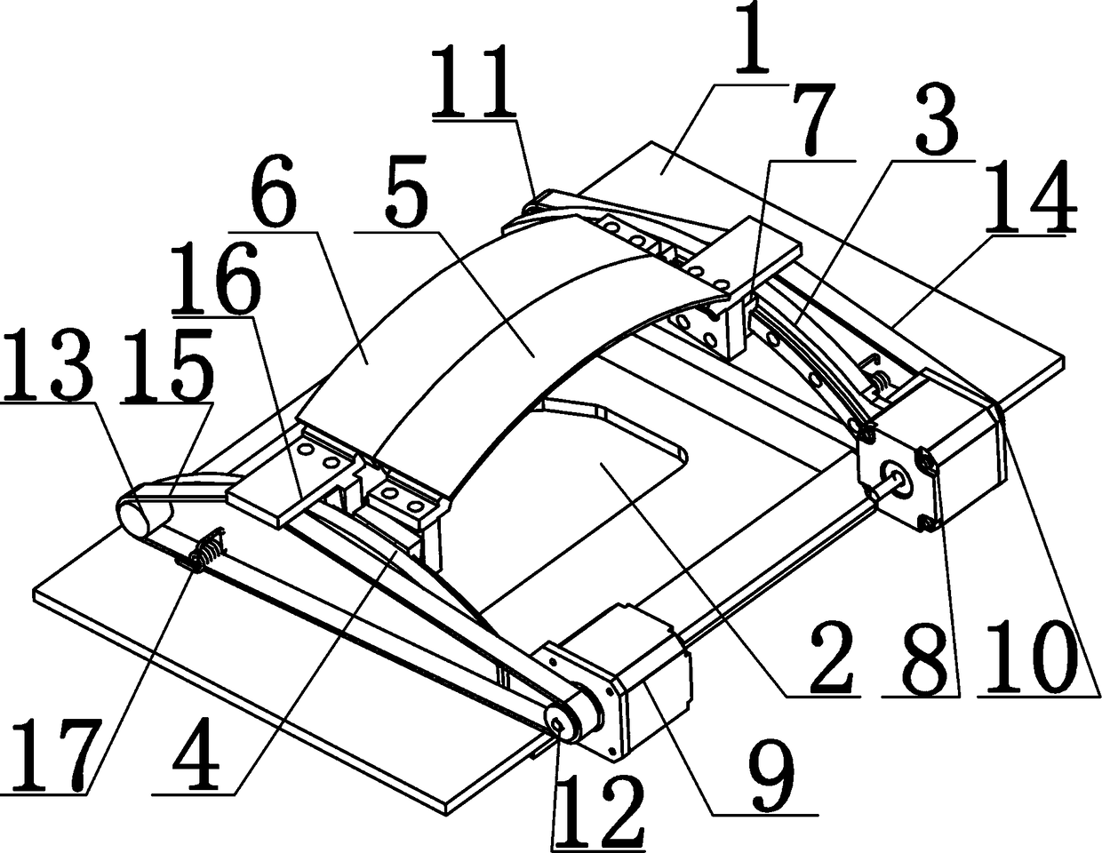
[0034]The transmission mechanism includes a first driving wheel 10 and a first driven wheel 11, a second driving wheel 12 and a second driven wheel 13 which are set in cooperation, and the first driving wheel 10 and the second driving wheel 12 are respectively arranged on the first On the motor shafts of the motor 8 and the second motor 9, the first motor 8 and the second motor 9 are respectively arranged on the front end of the case cover 1 on the left side and the right side of the through hole 2, and the first driven wheel 11 and the second The two driven wheels 13 are respectively arranged on the rear end of the case cover 1 on the left side and the right side of the through hole 2, and the outer sides of the first driving wheel 10 and the first driven wheel 11 are provided with a first synchronous belt 14. The outer sides of the two driving wheels 12 and the second driven wheel 13 are provided with a second synchronous belt 15, and the first synchronous belt 14 and the sec...

Embodiment 2

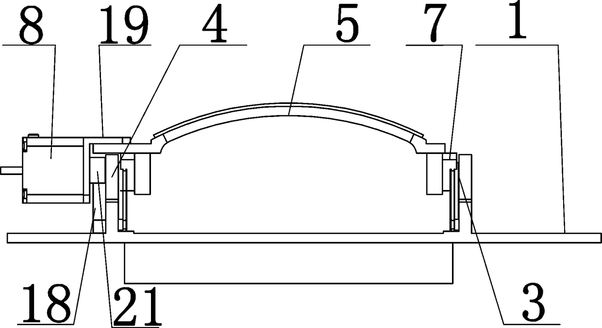
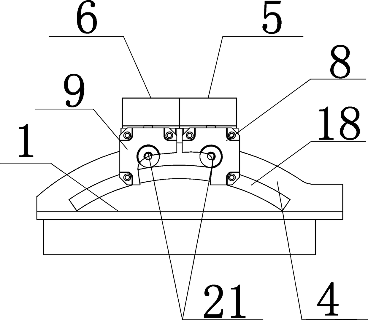
[0040] The transmission mechanism includes an arc rack 18 arranged on the side of the first arc guide rail 3 facing away from the through hole 2, and the arc rack 18 has the same radian as that of the first arc guide rail 3; The left ends of the optical shutter plate 5 and the second optical shutter plate 6 are respectively connected with a first transition plate 19 and a second transition plate 20, and the sides of the first transition plate 19 and the second transition plate 20 are respectively provided with a first motor 8 and the second motor 9, the output shafts of the first motor 8 and the second motor 9 are respectively sleeved with gears 21, and the first motor 8 and the second motor 9 connect with the arc-shaped teeth through the gears 21 and Bar 18 engages.

[0041] The first transition plate 19 and the second transition plate 20 are symmetrically arranged inverted L-shaped bent plates, and the two inverted L-shaped bent plates are arranged opposite to each other at ...


PUM


Abstract

The invention relates to a CT pre-collimator, and the pre-collimator comprises a collimator box, wherein the center of a box cover of the collimator box is provided with a through hole. The box cover is provided with a first arc-shaped guide rail and a second arc-shaped guide rail, which are parallel to each other, are disposed at the left and right side of the through hole and are located at the front and rear parts of the box cover. A first optical gate plate and a second optical gate plate, which are parallel to each other and perpendicular to the first and second arc-shaped guide rails, are disposed between the first and second arc-shaped guide rails, wherein two ends of each optical gate plate cooperate with the first and second arc-shaped guide rails through sliding blocks. The first and second optical gate plates are respectively connected to a first motor and a second motor through a transmission mechanism. The pre-collimator achieves the collimation simulation through the arc-shaped guide rails, and X-rays arriving at a detector are uniform in width. The utilization rate of rays is high, the radiation dosage is small, and there is no image quality problem and image artifact caused by scattered rays. The first and second optical gate plates can be operated independently. The pre-collimator is compact in overall structure, is small in occupied space, is low in cost, and is high in work efficiency.

Description

technical field [0001] The invention belongs to the technical field of particle or ionizing radiation processing technology; irradiation device; gamma ray or X-ray microscope, and particularly relates to a front collimator for CT with high ray utilization rate and no image quality problems and artifacts caused by scattered rays . Background technique [0002] The collimator in CT equipment belongs to an optical element used for input and output of optical fiber communication optical devices, and is mainly used to convert divergent light into parallel light through a structure similar to a convex lens. Generally, there are two front and rear collimators in CT equipment, among which the front collimator is mainly arranged at the front end of the X-ray tube to determine the thickness of the CT scanning slice. [0003] In the prior art, the shutter plate (curved plate or flat plate) of the collimator is generally installed on a linear guide rail and moved through a screw drive ...

Claims


Application Information

Patent Timeline
Patent Type & Authority Patents(China)
IPC IPC(8): G21K1/04
CPCG21K1/043
Inventor 潘险峰徐琴张铁
Owner 四川明峰医疗科技有限公司
Learn More