
High-resolution radar image enhancement method for aiming at vehicle observation scene

A radar image, high-resolution technology, used in image enhancement, image analysis, image data processing, etc., can solve problems such as high-resolution image filtering failure, and achieve enhanced image quality, good noise filtering, and edge detail retention capabilities. Effect

Inactive Publication Date: 2017-04-26
NANTONG UNIVERSITY +1
View PDF2 Cites 6 Cited by
  • Summary
  • Abstract
  • Description
  • Claims
  • Application Information

AI Technical Summary

Problems solved by technology

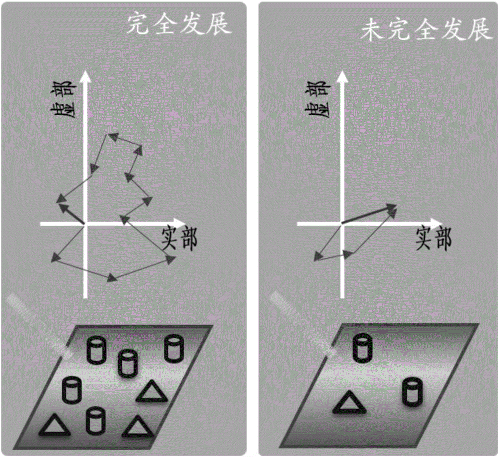
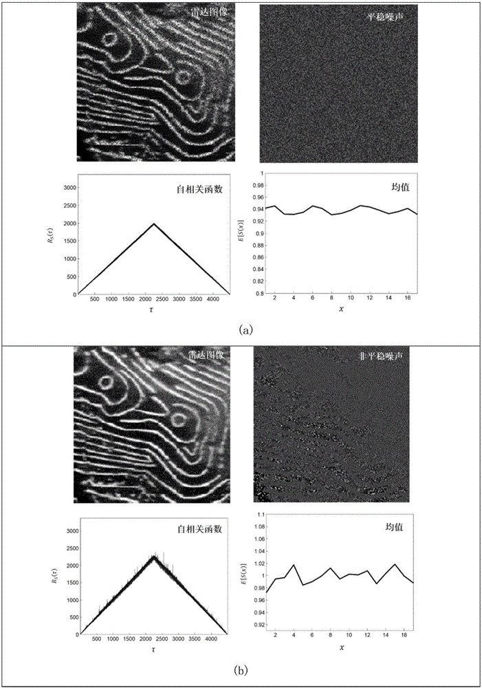
Especially for the vehicle observation scene, the radar image is non-uniform, so the assumptions of the Goodman model are no longer valid
The above existing methods are invalid for high-resolution image filtering

Method used


Image

  • High-resolution radar image enhancement method for aiming at vehicle observation scene
  • High-resolution radar image enhancement method for aiming at vehicle observation scene
  • High-resolution radar image enhancement method for aiming at vehicle observation scene

Examples


example 1

[0094] Such as Figure 5 , is a schematic diagram of the data to test the method. The left picture is the standard test image Barbara used for simulation. The image on the right is a real high-resolution radar image of a scene with vehicle observations.

[0095] Such as Image 6 , is the effect diagram of applying this method on the simulation data. The previous column is the effect diagram before and after filtering, and the next column is the multiplicative noise diagram obtained before and after filtering. Compared with traditional model algorithms, the inventive method has good ability to filter out noise and maintain edge details. The multiplicative noise image filtered out by this method shows that the noise is non-stationary. Secondly, for the simulated radar image, the original noise-free standard image is known, and the peak signal-to-noise ratio (PeakSignal to Noise Ratio, PSNR), structure similarity (Structure Similarity, SSIM) and edge preservation β can be use...

Embodiment 2

[0099] Such as Figure 7 , is a schematic diagram to test the ability of the algorithm to describe the actual data distribution. It can be seen from the figure that these conclusions can be clearly drawn: 1) These high-resolution radar radars no longer satisfy the Goodman assumption, and Nakagami cannot effectively fit the data distribution; 2) The lognormal distribution is more effective in describing these Inhomogeneous high-resolution radar images, but not perfect fitting; 3) The mixed lognormal model proposed by the method of the present invention can perfectly fit the distribution of these data.

[0100] Figure 8 It is a schematic diagram of the results of applying the algorithm to the real vehicle observation scene data; the upper column in the figure is the effect map before and after filtering, and the next column is the multiplicative noise map obtained before and after filtering. The multiplicative noise image filtered by this method shows again that the noise of ...


PUM


Abstract

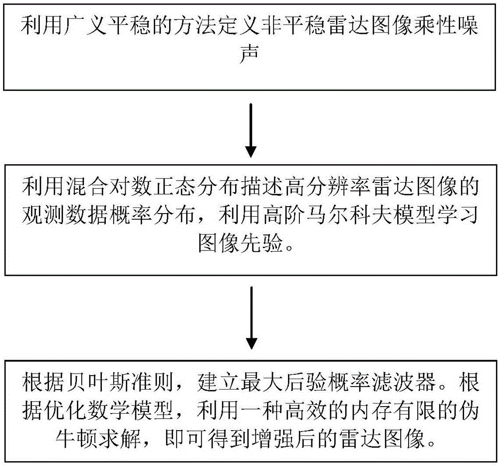
The invention provides a high-resolution radar image enhancement method for aiming at a vehicle observation scene. The high-resolution radar image enhancement method comprises the following steps of 1), defining multiplicative noise in a non-stationary radar image according to a generalized stationary method; 2), leading an image prior probability according to a high-order Markov model, describing observation data probability distribution of the high-resolution radar image according to the prior probability through logarithm normal distribution description, and deriving likelihood probability function distribution of an image according to the observation data probability distribution and the multiplicative noise model; and 3), establishing a Maximum-a-posteriori filter according to a Bayes principle, and performing optimization problem processing for obtaining a reinforced radar image. The high-resolution radar image enhancement method has beneficial effects of overcoming a problem of filtering failure to non-stationary noise of the high-resolution image according to a traditional method, and effectively improving quality of the high-resolution radar image in a vehicle observation scene.

Description

technical field [0001] The invention relates to a high-resolution radar image enhancement filtering technology for a vehicle observation scene, and in particular designs a high-resolution radar image enhancement method for a vehicle observation scene. Background technique [0002] Due to the inherent coherent nature of microwave imaging radar, radar images are affected by a type of multiplicative noise called coherent speckle. Therefore, radar image noise filtering is an important preprocessing step in the stage of radar image feature extraction. Currently existing microwave radar image filtering methods mainly include: spatial estimation filtering methods, such as Lee filtering and Frost, Kuan filtering; based on maximum a posteriori probability estimation, such as Gamma-MAP; wavelet domain filtering methods; non-local mean NLM filtering methods, Such as PPB, Radar-BM3D, and FANS etc. [0003] The existing methods above are mainly applicable to low-resolution radar image ...

Claims


Application Information

Patent Timeline
IPC IPC(8): G06T5/00
CPCG06T2207/20024G06T2207/20081G06T2207/10044G06T2207/30168G06T5/70
Inventor 许致火施佺黄新明孙玲施佳佳
Owner NANTONG UNIVERSITY
Learn More