
Testing system for electric vehicle's wireless power charging system

A technology for wireless charging and electric vehicles, which is used in electric power measurement through current/voltage, battery circuit device, non-electric variable control, etc. , It is difficult to achieve multi-channel data synchronous recording and other problems

Active Publication Date: 2017-04-26
GAC AION NEW ENERGY AUTOMOBILE CO LTD
View PDF5 Cites 34 Cited by
  • Summary
  • Abstract
  • Description
  • Claims
  • Application Information

AI Technical Summary

Problems solved by technology

[0003] The test scheme of the traditional wireless charging system mainly uses discrete instruments for limited measurement. In order to test the efficiency of the wireless charging system under the alignment and misalignment of the transmitting coil and the receiving coil, the relative position of the coil is adjusted manually, and then the wireless charging process is carried out. Testing, this method is not only inefficient, but also cannot realize the development and testing of some advanced charging control programs that require real-time control of the coil position, and the test coverage of the wireless charging system is relatively small, such as only testing the power circuit part and lacking Related control signals and control timing tests, and it is difficult to achieve synchronous recording of multi-channel data in each link, such as synchronous recording of communication signals and voltage and current signals of each link
[0004] In summary, the traditional wireless charging system test has the defect of low test efficiency

Method used


Image

  • Testing system for electric vehicle's wireless power charging system
  • Testing system for electric vehicle's wireless power charging system
  • Testing system for electric vehicle's wireless power charging system

Examples


Embodiment Construction

[0016] Embodiments of a test system for a wireless charging system for an electric vehicle will be described below in conjunction with the accompanying drawings.

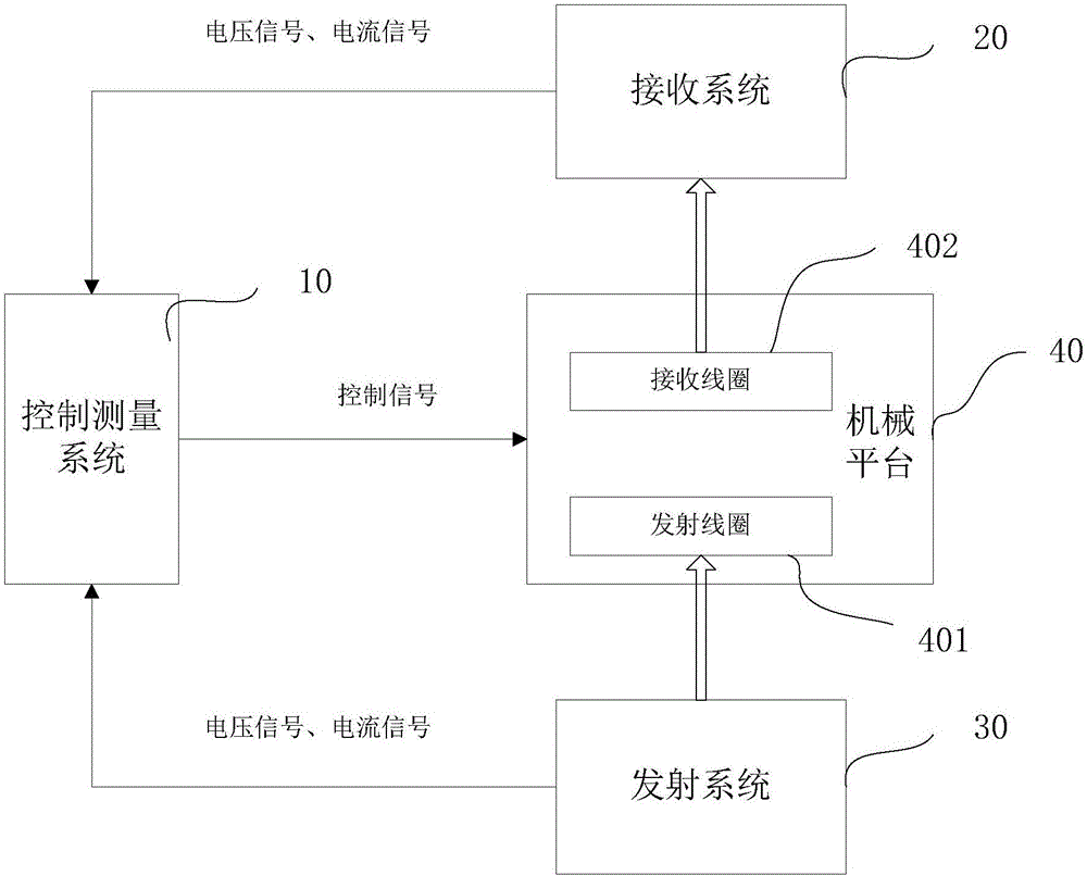
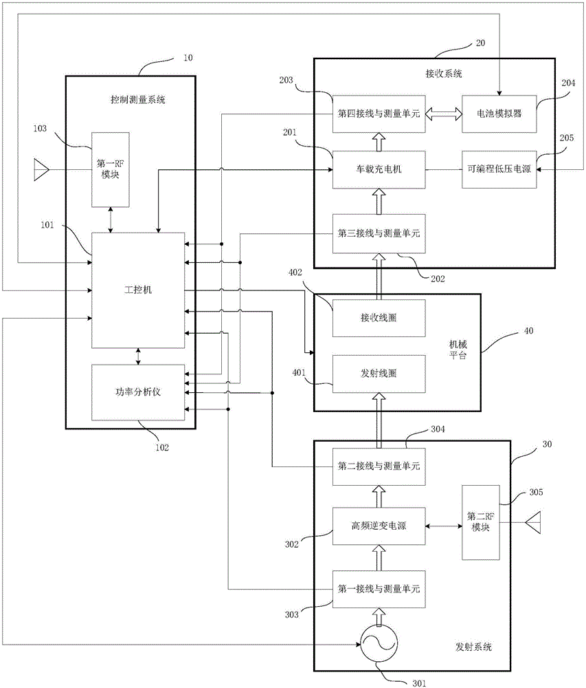
[0017] refer to figure 1 , figure 1 It is a schematic structural diagram of a test system for a wireless charging system for electric vehicles, including: a control and measurement system 10, a receiving system 20, a transmitting system 30, and a mechanical platform 40;

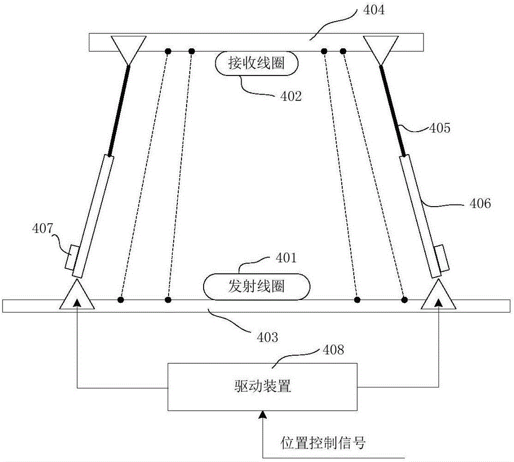
[0018] The mechanical platform 40 is provided with a matching transmitting coil 401 and receiving coil 402;

[0019] The control measurement system 10 is respectively connected to the receiving system 20, the transmitting system 30 and the mechanical platform 40; the transmitting system 30 is connected to the transmitting coil 401, and the receiving system 20 is connected to the receiving coil 402;

[0020] The transmitting system 30 outputs power to the transmitting coil 401, converts it into electromagnetic energy, and transmits it to the recei...


PUM


Abstract

The invention relates to a testing system for electric vehicle's wireless power charging system, comprising a control and measurement system, a receiving system, an emitting system and a mechanical platform. The mechanical platform is provided with an emitting coil and a receiving coil that are matched with each other. The control and measurement system is connected with the receiving system, the emitting system and the mechanical platform respectively. The emitting system is connected with the emitting coil; the receiving system is connected with the receiving coil; the emitting system outputs power to the emitting coil, converts it into electromagnetic power and transmits it to the receiving coil. The receiving coil converts the electromagnetic power into electric power and transmits it to the receiving system. The control and measurement system outputs a control signal to the mechanical platform and adjusts the relative position of the emitting coil to the receiving coil. The control and measurement system measures the voltage signals and the current signals of the emitting system and the receiving system respectively; and based on the voltage signals and the current signals, it is possible to conduct testing for an electric vehicle's wireless power charging system. The testing system of the invention is capable of making testing more automatic and increasing the testing efficiency.

Description

technical field [0001] The invention relates to the technical field of electric vehicles, in particular to a test system for a wireless charging system of an electric vehicle. Background technique [0002] Wireless charging has the characteristics of good safety, high degree of automation, no mechanical contact, and long service life of parts. It is one of the development directions of electric vehicle charging technology. The wireless charging method of electric vehicles is to use electromagnetic induction or electromagnetic vibration to realize the non-contact transmission of electric energy through the transmitting coil of the transmitting system and the receiving coil of the receiving system, so as to charge the battery of the electric vehicle. In the development process of the electric vehicle wireless charging system, it is necessary to test the wireless charging system, collect relevant data during the charging process in real time, and process and analyze them. Acco...

Claims


Application Information

Patent Timeline
IPC IPC(8): G01R21/06G01R19/00G05D3/12H02J50/10
CPCG01R19/0046G01R21/06G05D3/125H02J7/025
Inventor 赵小坤韩祥刘秀田夏铸亮裴锋
Owner GAC AION NEW ENERGY AUTOMOBILE CO LTD
Learn More